Geology Reference
In-Depth Information
angle to the trend of the faults (Fig. 8.31a). Structure contour maps on the faults show
them to overlap in the relay zone (Fig. 8.31b). Both faults end at tip lines that define the
ends of the relay zone. The extent of the faults may be large, both updip and downdip, and
the tip lines may be straight or curved.
8.6.2
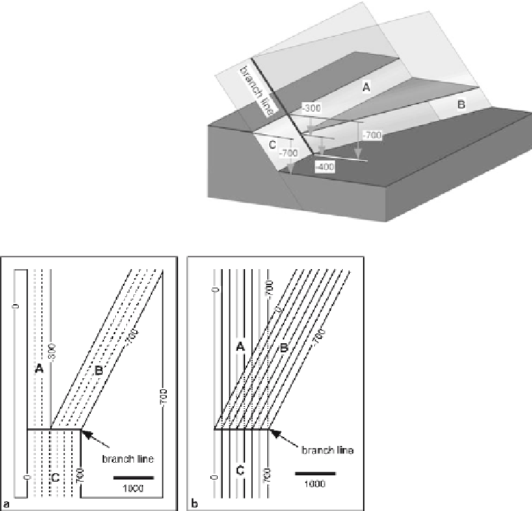
Branching Fault
The intersection of two faults (Fig. 8.32) occurs along a branch line (Boyer and Elliott
1982). Some of the displacement is transferred from the main fault to the branch fault
at the intersection. Displacement is conserved at the branch line (Ocamb 1961). As can
be seen from Fig. 8.32, at the branch line, the throw of the largest fault will be equal to
the sum of the throws on the two smaller faults. All the faults may change throw inde-
pendently away from the branch line.
Fig. 8.32.
Displacement transfer at a
branch line on a normal fault.
Fault surfaces are
shaded
. The
total throw is constant at the
branch line. In this example
faults
A
and
C
are a single
plane; fault
B
is the branch
Fig. 8.33.
Structure contour maps of a
branching normal fault, based
on the geometry of the struc-
ture in Fig. 8.32. Both maps
are at the same scale.
a
Struc-
ture contours on the displaced
marker horizon (
solid lines
)
and on the faults (
dashed lines
).
b
Structure contours on por-
tions of the three fault planes;
contours on fault
A
are
dashed
where the plane lies below
fault
B
. Fault planes
A
and
C
are the same