Geology Reference
In-Depth Information
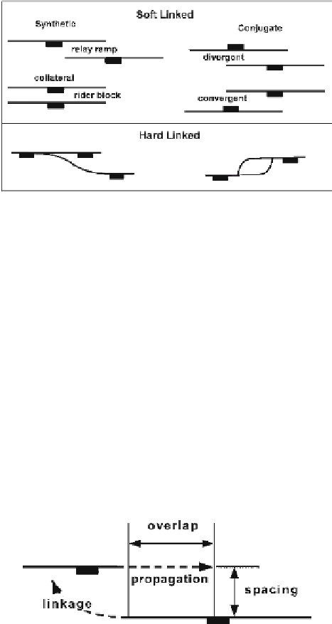
Fig. 8.27.
Displacement-transfer geom-
etries on normal faults in map
view. (After Morley et al. 1990)
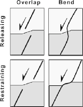
Fig. 8.28.
Displacement-transfer geom-
etries on normal faults in cross
section
Fig. 8.29.
Possible evolution of a relay
zone into a hard link.
Dashed
arrows
indicate fault propaga-
tion directions
Soft links may evolve into hard links as displacement increases and the faults grow
longer. Faults may propagate in their own plane or curve to intersect (Fig. 8.29). In
general, a wide spacing between the propagating faults favors overlap and a small spacing
favors linkage.
In the following sections the basic patterns of fault-to-fault displacement transfer
are examined. All types of faults show the same forms of displacement transfer. The
examples given will mainly be normal faults because they are easy to visualize, but the
same principles and terminology can be applied to reverse and strike-slip faults.