Geology Reference
In-Depth Information
Structures may develop independently across some fault zones and so may not directly
correlate across the fault. That the fold geometry is the same on both sides of the fault
in Fig. 8.21 supports the concept that a pre-existing fold has been cut by a later fault
and that the arrows connecting hinge lines (Fig. 8.21b) represent the slip.
If croscutting features are present at the fault surface, an Allan diagram will make both
the slip and rotational components obvious and readily measurable. Both vein-bed and
vein-vein intersections can be correlated across the fault in Fig. 8.22. As a result of the
rotational displacement on the fault, each correlated point has a different net slip.
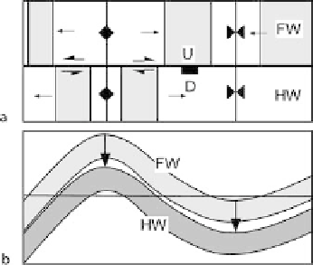
Fig. 8.21.
Anticline-syncline pair cut by a nor-
mal fault.
a
Map. The
shaded
bed is
the same on both sides of the fault.
Full arrows
show bedding dips,
half
arrows
show strike separations, not
slip.
b
Fault cutoff map of hanging-
wall (
darker shading
) and footwall
cutoffs. The
horizontal line
is the
line of intersection of the outcrop
map and cutoff map.
Arrows
show
the hangingwall slip vectors of the
anticlinal and synclinal hinge lines
and indicate pure dip slip
Fig. 8.22.
Rotational fault displacement on a
fault cutoff map. Superimposed fault-
surface sections of hangingwall (
un-
shaded
) and footwall (
shaded
). Hori-
zontal footwall beds labeled
A
and
B
rotate to
A'
and
B'
; veins
C
and
D
ro-
tate to
C'
and
D'
.
Arrows
show hang-
ingwall slip of correlated bed-vein
intersection points. Fault slip is a
left-lateral reverse translation pro-
duced by a 15° clockwise rotation of
the hangingwall relative to the foot-
wall
Fig. 8.23.
Allan diagrams for
a
dip-slip
and
b
strike-slip dislocation-
model faults