Geology Reference
In-Depth Information
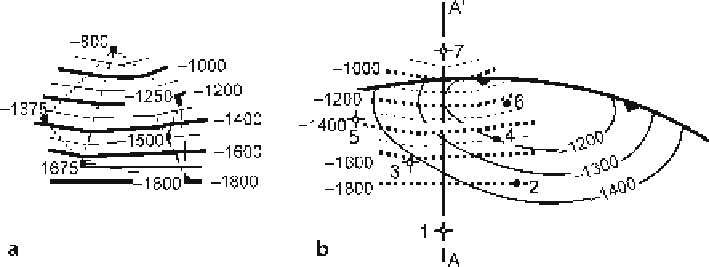
Fig. 6.44.
Fault-surface map based on the wells in Fig. 6.34 that cut the fault.
a
Points
give well locations
and depths of fault cuts;
dotted lines
connect the nearest neighbors for contouring. Structure contours
(
solid lines
) are derived by triangulation.
b
Structure contours on the fault (
dotted lines
) from a, super-
imposed on the structure contours of horizon E (
solid lines
) to show their parallelism to the fault trace
Where sufficient data are available, projection by contouring is equivalent to along-
plunge projection. For example, the wells in Fig. 6.34 can be projected to the line of
section by contouring without knowing the plunge amount or direction. To demon-
strate this, the fault in Fig. 6.34 is contoured. The wells are inspected individually to be
sure that each one shows only one fault cut, indicating that each well may cut the same
fault. The fault contours generated from the elevations of the fault cuts (Fig. 6.44a) are
smooth, as expected for a single fault. The fault contours superimposed on the original
map (Fig. 6.44b) give the projected elevations of the fault along the line of section. The
contours trend almost east-west, parallel to the plunge direction of the fold. A cross
section of the fault along A-A' in Fig. 6.44b would be nearly identical to that in Fig. 6.34c.
Each map horizon could be mapped to give a 3-D reconstruction of the structure which
could then be sliced to create a cross section. When surfaces are mapped separately
from sparse data, the spacings between them (thicknesses) are likely to show irregular
variations. These variations should be corrected in the final cross section to maintain
constant thicknesses (assuming it is geologically appropriate).
6.7
Dip-Domain Mapping from Cross Sections
The construction of maps from cross sections is a valuable technique where the struc-
ture is complex and/or the folds are conical. For cylindrical folds and faults the dip
domains can be constructed is sections normal to the axis and linked together. Coni-
cal folds pose a special problem because no cross section can be drawn that will pre-
serve bed thickness everywhere. The most general method is to define and map the
dip domains in three dimensions. The approach will be illustrated here with the simple
conical fold introduced in Sect. 5.3.
The horizontal domains in the conical fold (Figs. 6.45, 6.46) show unexaggerated
thickness only in a vertical section. Only sections normal to the hinge lines show the
unexaggerated thicknesses on the limbs (Fig. 6.46), requiring two different cross-sec-