Geology Reference
In-Depth Information
Fig. 6.36.
Plunge lines in a cylindrical
fold. The lines are parallel to
the plunge and points along
the lines mark elevations.
(After De Paor 1988)
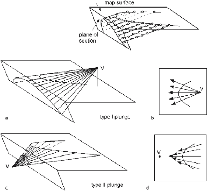
Fig. 6.37.
Plunge lines in conical folds.
V
Fold vertex.
a
Perspective view of type I fold.
b
Map view of
plunge lines in type I fold.
Arrows
point down the plunge direction.
c
Perspective view of type II fold.
d
Map view of plunge lines in type II fold.
Arrows
point down the plunge direction
provide an effective means for quantitatively describing and projecting the 3-D geometry
of a fold. A series of plunge lines defines the shape of the structure (Fig. 6.36). The
plunge line for a cylindrical fold is parallel to the fold axis and is the same direction for
every point within the fold (Fig. 6.36). Each plunge line in a conical fold has its own
bearing and plunge (Fig. 6.37). The plunge lines fan outward from the vertex. In a type I
conical fold (Fig. 6.37a,b) the plunge is away from the vertex and in a type II fold the
plunge is toward the vertex (Fig. 6.37c,d). Plunge line directions in conical folds are
best determined from the tangent diagram as described previously (Sect. 5.2.2).
A plunge line lies in the surface of the bed. Begin the projection by drawing a line
on the map parallel to the plunge through the control point to be projected. Starting
from the known elevation of the control point, mark spot heights (Fig. 6.38) spaced
according to
H
=
I
/tan
,
(6.11)
φ