Geology Reference
In-Depth Information
To properly control the geometry of a cross section at depth, data may be needed at a
long distance laterally from the area of interest (Fig. 6.26). For example, in order to cor-
rectly locate the crest of an anticline at depth, dips are needed from the adjacent synclines.
If the last dip in the anticline (Fig. 6.26) was collected at A, then the steep limb of the
structure would be drawn with the long dashed lines and the crest on the lowest horizon
would be at the location of the incorrect well. Using the dips at B, C, and D, the structure
is drawn with the solid lines, and the crest is found to be at E (Fig. 6.26). This is a general
property of cross-section geometry and also applies to dip-domain constructions.
6.4.2.2
Dip Interpolation
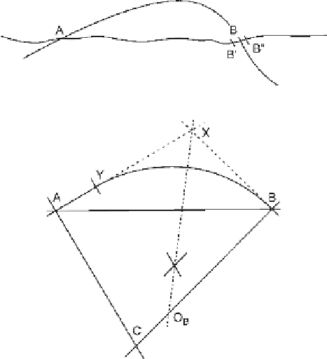
Frequently the predicted geometry and the bed locations do not agree. The predicted
location of horizon A (Fig. 6.27) on the opposite limb of the anticline is at B, but that
horizon may actually crop out at B' or B''. This result means that insufficient data are
available to force a correct solution. It is necessary to modify the data or to interpolate
intermediate dip values between A and B in order to make the horizon intersect the
section at B' or B''. Two methods of dip interpolation will be given; the first is to inter-
polate a planar dip segment and the second is to interpolate an intermediate dip.
The simplest method is to insert a straight line segment (AY, Fig. 6.28) between the
two arc segments that produce the disagreement. This method is usually successful
and provides an end-member solution. The procedure is from Higgins (1962):
Fig. 6.27.
Cross section showing the mis-
match between the predicted
location of the key bed at
A
and its mapped location (
B'
or
B"
) at
B
. (After Busk 1929)
Fig. 6.28.
Interpolation using a straight
line with a circular arc. (After
Higgins 1962)