Geology Reference
In-Depth Information
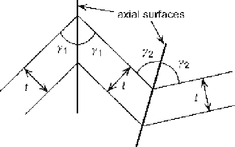
Fig. 6.15.
Dip-domain fold hinges in a
constant thickness layer.
t
Bed
thickness;
γ
1
-half-angles of the
interlimb angle
beds, the axial surface bisects the interlimb angle between adjacent dip domains
(Fig. 6.15). This maintains constant bed thickness. If the beds change thickness across
the axial surface, then the axial surface cannot bisect the hinge. The technique is de-
scribed here in the context of constant thickness beds. The technique is the same for
beds that change thickness except that the axial surfaces do not bisect the hinges. See
Eq. 5.13 for a method to calculate the axial surface orientation in folds that do not
maintain constant bed thickness (see also Gill 1953).
6.4.1.1
Method
The following steps outline the dip-domain construction technique.
1. On the map or cross section, define the dip domains and locate the boundaries
between domains as accurately as possible (Fig. 6.16a). A certain amount of vari-
ability from constant dip is expected in each domain (perhaps a 2-5° range).
2. Define the axial surfaces between domains (Fig. 6.16b). If bed thickness is constant,
the axial surfaces bisect the hinges, but if bed thickness changes are known, use
Eq. 5.13 to find the dips of the axial surfaces. Where axial surfaces intersect, a dip
domain disappears and a new axial surface is drawn between the newly juxtaposed
domains (for example, locations X in Fig. 6.16b). Note that a single fold is likely to
have multiple hinges, as illustrated in Fig. 6.16.
3. Draw a key bed or group of beds through the structure, honoring the domain dips and
the stratigraphic tops (Fig. 6.16c). Sometimes the data do not allow a single key bed to
be completed across the whole structure. Shifting up or down a few beds to a new key
bed will usually allow the section to be continued. Note that axial-surface intersections
do not necessarily coincide with named stratigraphic boundaries. It is usually helpful
to draw an horizon through the axial-surface intersection points (Fig. 6.16c).
4. Complete the section by drawing all the remaining beds with their appropriate
thicknesses (Fig. 6.16c).
5. If desirable on the basis of the structural style, round the hinges an appropriate
amount using a circular arc with center on the axial surface, or a spline curve.