Geology Reference
In-Depth Information
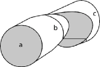
Fig. 6.4.
Cross-section lines across a
cylinder offset along an ob-
lique fault
reveal the basic geometry of the cylinder. A cross section at b that crosses the fault will
be very difficult to interpret until after the basic geometry is known from sections a
or c. The simplest method for constructing the structure along section b would be to
project the geometry into it from the unfaulted parts of the cylinder.
6.2.2
Choosing the Section Dip
Only a cross section perpendicular to the plunge (the normal section) shows the true
bed thicknesses. In all other sections the thicknesses are exaggerated. This is impor-
tant if the section is going to be used for predictive purposes. The plunge of a cylin-
drical fold is the orientation of its axis, which can be found from the bedding atti-
tudes using the stereonet or tangent diagram techniques given in Sect. 5.2. A conical
fold does not have an axis and so, in the strict sense, there is no normal section. The
orientation of either the crestal line or the cone axis is an approximate plunge direc-
tion for a conical fold. On a structure contour map the trend and plunge of the crestal
line is readily identified. The plunge angle is given by the contour spacing in the plunge
direction.
Within a domain of cylindrical folding, changing the dip of the section plane is
equivalent to changing the vertical or horizontal exaggeration. This relationship is the
basis of the map interpretation technique known as down-plunge viewing. The map
pattern in an area of moderate topographic relief represents an oblique, hence exag-
gerated, section through a plunging structure. Viewed in the direction of plunge, the
map pattern becomes a normal section (Mackin 1950).
The down-plunge view of a fault should give the correct cross-section geometry and
the sense of the stratigraphic separation. The plunge direction of a fault is parallel to
the axis or crest or trough line of ramp-related folds or drag folds. If the fault is listric
or antilistric, the plunge direction should be the axis of the curved surface, just as if it
were a folded surface. If the fault is planar and there are no associated folds, the appro-
priate plunge direction is parallel to the cutoff line of a displaced marker against the
fault (Threet 1973).
If a vertical cross section is constructed normal to the trend of the plunge, the ver-
tical exaggeration due to the plunge angle can be removed by rotating the section using
the method given in Sect. 6.5. The same approach can be used to convert a map view
into a normal section.