Geology Reference
In-Depth Information
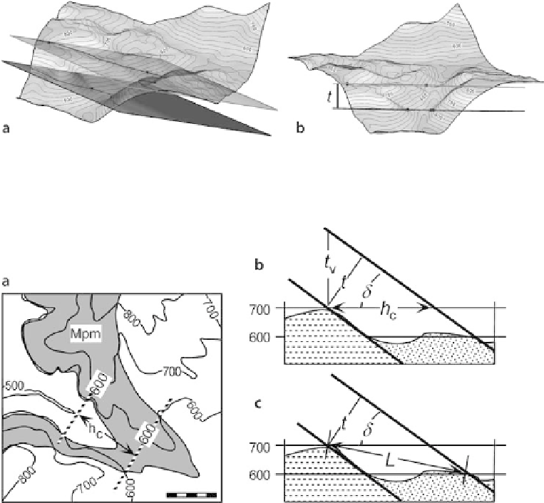
Fig. 4.4.
Oblique views of planar unit boundaries cutting a topographic surface. Map view is in Fig. 4.5a.
a
Upper and lower bed surfaces, view toward north.
b
View to northeast parallel to bedding showing
thickness,
t
Fig. 4.5.
Thickness measured between structure contours.
a
Structure contours at 600-ft elevation on the
top and base of a formation;
h
c
is perpendicular to structure contours (3-D views in Fig. 4.4).
b
Measurement
along a constant elevation on a vertical cross section in the dip direction.
c
Measurement between points
of different elevations on a vertical cross section in the dip direction. For explanation of
symbols
, see text
base of the unit are at different elevations (Fig. 4.5c), then the line on the map that
connects the upper and lower contours has the length
L
, and the thickness can be cal-
culated from Eq. 4.1. Equation 4.1 gives the same result as Eq. 4.8 for the special case
where
L
is horizontal.
The vertical thickness can readily be computed by taking the difference in elevation
between structure contour maps on the top and base of the unit at a given
xy
point
(Fig. 4.5b). Then the true thickness is calculated from Eq. 4.2, rewritten as
t
=
t
v
cos
δ
,
(4.9)
where
t
= true stratigraphic thickness,
t
v
= vertical thickness and
= dip.
δ