Biomedical Engineering Reference
In-Depth Information
Figure 3.14
Fiber length distribution for
carbon fibers removed from injection-
molded short carbon fiber-reinforced
PEEK by acid digestion.
18
16
14
12
10
8
6
4
2
0
Fiber Length (microns)
For some implant devices, the strength and stiff-
ness of short CFR PEEK may not be sufficient to
resist the considerable biomechanical loads placed
on the material, yet the implant developer may wish
to retain the MRI and CT compatibility of a polymer
system and avoid the use of metals. In such cases it
may be necessary to change the configuration of the
fibers such that they are longer and more concen-
trated. This requires a different approach to their
incorporation and processing.
120
100
80
60
40
20
0
0
100
200
300
400
500
600
700
Fiber Length (microns)
Figure 3.15
Cumulative fiber length distribution for
carbon fibers removed from injection-molded short
carbon fiber-reinforced PEEK by acid digestion.
3.3.2 Continuous CFR PEEK
By “continuous” it is not meant that the fibers are
infinitely long, they are just long in relation to their
diameter. A reinforcing fiber may be considered
“continuous” when the mechanical properties no
longer respond to increases in fiber length. The precise
length at which this occurs depends on a number of
factors, including the relative strength or stiffness of
the fiber and matrix and the quality of the interface
between them. It may be regarded that continuous
means longer than about 6 mm, but more typically in
practical deployment, continuous fibers run the entire
length, or width, of the manufactured part.
The mechanical properties of continuous fiber
reinforced PEEK depend on the orientation of the
fibers in the classical way, as described by Hull and
Clyne
[8]
, with maximum tensile properties achieved
parallel to the fiber alignment direction. Woven
and unidirectional fiber pre-preg materials (pre-
impregnated with polymer) are possible with PEEK
and composite products can be manufactured by
stacking these pre-pregs in specific orientations rela-
tive to some reference axis that optimize the
mechanical strength or stiffness of the manufactured
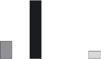
250
200
150
100
50
0
Cortical
Bone
CF PEEK-
OPTIMA
Compound
PEEK-
OPTIMA
Polyethylene
Figure 3.16
Tensile strength of PEEK-OPTIMA and
short carbon fiber-reinforced PEEK-OPTIMA compared
with cortical bone and UHMWPE (polyethylene).
Source: Invibio.
that short CFR PEEK-OPTIMA has a stiffness that
more closelymatches the stiffness of bone. This “bone-
like” stiffness is an important attribute of CF PEEK-
OPTIMA materials
for
reasons
described
in
Section 3.1
.