Biomedical Engineering Reference
In-Depth Information
including the bearing surface, as an alternative to
polyethylene. CFR-PEEK has a decades-long history
of biocompatibility
[51,94,95]
. As a bearing surface
with a ceramic femoral counter face, the material has
excellent wear resistance
[96,97]
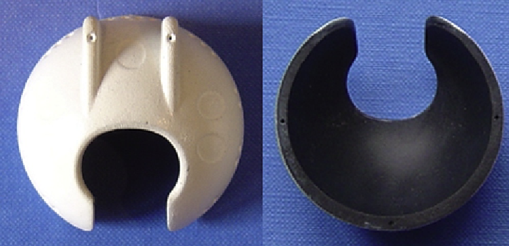
. Initial fixation of
the MITCH cup in the acetabulum is provided by two
superiorly directed fins that are part of the implant
structure. Long-term fixation is achieved by bone
ongrowth onto a hydroxyapatite coating applied over
a titanium bond coat (
Fig. 14.12
).
Because of the combined changes in design and
material properties between the clinically successful
Cambridge Cup and the new MITCH
trabecular bone based on the quantitative computed
tomography (QCT) data and reported density
e
modulus relationships
[99]
. The model was subjected
to verification and validation studies, as described
previously
[63,98]
.
A Cambridge Cup FE model (266,690 brick and
27,408 shell elements; 294,409 nodes) was also
constructed by incorporating a 54.5 mm outer
diameter (OD) horseshoe-shaped cup (
Fig. 14.13
)
and a large-diameter (45 mm) femoral head. The cup
consisted of a 3-mm-thick UHMWPE bearing
surface and a 1.5-mm-thick backing of 30% carbon-
fiber-reinforced polybutyleneterephthalate (16.6 GPa)
[90]
. A MITCH
-PCR Cup FE model (157,404
brick elements and 28,746 shell elements; 174,621
nodes) was also constructed with an internal bearing
diameter of 48 mm and OD of 54.2 mm (
Fig. 14.13
).
The horseshoe-shaped cup consists of a 30% carbon-
fiber-reinforced PEEK (12.8 GPa) bearing with
varying thickness between 2 and 3 mm, and two fins,
as previously described.
A peak joint reaction force of 3 kN was applied
through the center of the femoral head for all models.
Distributed nodal pelvic muscle forces were also
taken into account, as described previously
[63]
. The
FE models were analyzed using the FE analysis
solver LS-DYNA (Livermore Software Technology
Corporation, Livermore, CA). In a previous study
[63]
, a conventional metal-backed hemispherical cup
hip model (4 mm Ti alloy backing and 8 mm
UHMWPE liner) was also developed. We compared
the periacetabular stress (maximum compressive)
and strain (von Mises) fields around the Cambridge
and MITCH
-PCR Cups with those from the
conventional hip arthroplasty.
-PCR design,
we conducted a periacetabular stress transfer analysis
of the two designs. We used a previously developed
high-resolution computational model of the pelvis
[63,98]
to evaluate the periprosthetic stress and strain
fields around the Cambridge and MITCH
-PCR
Cups. We also compared our load transfer findings to
previously published
[63]
results for hemispherical
cementless acetabular components.
A three-dimensional FE model of the natural
bilateral hip was generated based on the geometry
and material properties of a 45-year-old female donor
hip with no known bone disorder (Investigational
Review Board approved). One-millimeter-thick slice
images of the hip (0.781 mm
0.781 mm resolution)
were obtained using a CT scanner. Linear brick
elements were used to model the pelvic, sacral, and
femoral trabecular bone, while linear shell elements
were used to model a 1-mm-thick cortical shell
around the pelvis. The final mesh consisted of
139,616 brick elements and 26,776 shell elements
(154,533 nodes). Nonhomogeneous, isotropic, linear
elastic material properties were assigned to the
Figure 14.12
MITCH
-PCR Cup.