Biomedical Engineering Reference
In-Depth Information
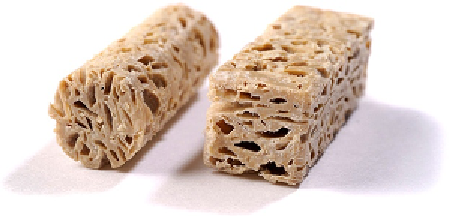
Figure 12.11
CT-scanned porous
PEEK showing samples with
small pores and large pores and
bovine trabecular bone (lower) as
a control sample comparison
[40]
.
Images courtesy of A. Poulsson
and D. Eglin, AO Research
institute, Davos, Switzerland.
(b)
(a)
(c)
subsequently be machined, prior to leaching in hot
deionized water. Porous materials were manufac-
tured as a bulk blend and processed by this approach
(
Fig. 12.14
) and then analyzed by micro-CT
(
Fig. 12.15
). The results of this demonstrated an
improvement in connective density (42mm
3
)
compared with that of the “small” pore (1400 mm
3
)
and “large” pore (87 mm
3
) samples described in the
previous case studies, although connectivity still did
not reach that of trabecular bone (~7 mm
3
). The
typical pore characteristics of the material showed
a porosity of 51%, wall thickness of 312
m
m, and
Figure 12.12
Comparison of the static compressive
strength of small and large porous PEEK materials
[40]
.
The process described in this final case study can
be carried out in a mold using a bulk blend of the
materials, preheating to aid heat transfer and then
melting the PEEK fully. This near net shape can
Figure 12.14
Example of a shape that was molded
using PEEK micropellets with a soluble filler. The shape
could then be refined using trimming and the space
filler removed with water.
Figure 12.13
Samples of porous PEEK with large
porosity attempting to match to trabecular bone.