Biomedical Engineering Reference
In-Depth Information
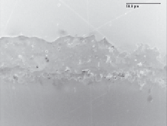
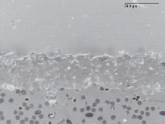
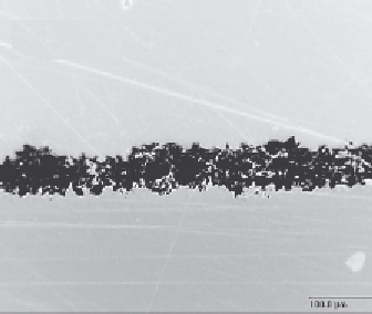
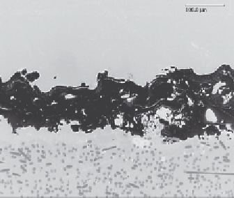
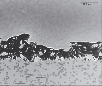
Figure 9.14
Cross-sectional
micrographs of different Ti
coatings on PEEK-based
substrate: (a) HA APS coating on
LT1; (b) HA APS coating on
LT1CA30; (c) low-roughness, Ti
APS coating on LT1; (d) high-
roughness, Ti APS coating on
LT1CA30; (e) high-roughness, Ti
VPS coating on Endolign
; (f)
high-roughness, Ti APS coating
on Motis
(a)
(b)
.
(c)
(d)
(e)
(f)
ether groups of the PEEK molecular chain did not
vary.
The thermal properties are unaffected as well, as
illustrated in
Table 9.5
, which summarizes the values
of glass transition temperature and melting point for
two substrates, obtained with DSC measurement on
samples of material taken from the treated surface.
A thorough mechanical investigation was carried
out on the substrates
[91
e
94]
. As shown in
Fig. 9.20
,
static tensile strength is not affected by the coating
process for the tested substrates. Similar strength
values were detected for all the samples when
measures were normalized to effective substrate
cross-section. According to the values reported in
Fig. 9.21
, coatings do not contribute to specimen
strength
cross-section). On the other hand, elongation is
reduced by the plasma spray coating process, espe-
cially for PEEK (about
40%) (
Fig. 9.22
).
Fatigue investigations gave two different
scenarios: CFR-PEEK seems relatively insensitive
to three different types of coatings as shown in
Fig. 9.23
, whereas plain PEEK seems affected by
Ti coatings and not by HA coating (
Fig. 9.24
). A
possible explanation for this behavior was deduced
after optical investigations of coating status and by
monitoring substrate strains during fatigue cycling.
Coatings onto CFR-PEEK appeared well adherent
to substrate and their integrity was confirmed along
the fatigue test with run-out fixed at 1 million
cycles. Strains during fatigue cycling for CFR-
PEEK were less than 0.5%. In contrast, strains are
(substrate
cross-section
plus
coating