Graphics Programs Reference
In-Depth Information
5.
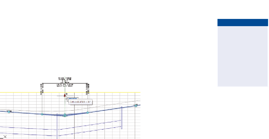
Click the triangular grip, and drag it upward to a location just below
the top edge of the profile view grid, as shown in Figure 2.6.
◀
Notice the 3D view
(bottom-right) of the
road updates, including
the height of the Inlet
2 drain. In the profile
view (top-right), the top
of the drain is elevated
to match the road.
6.
Save and close the drawing.
You can view the results of successfully completing this exercise by opening
Object Relationships - Complete.dwg
.
FiGuRE 2.6
Grip-editing the profile
This simple exercise illustrates the power of relationships between objects. The
ease with which you just updated the design may cause you to take the underlying
processes for granted; however, there is a lot happening behind the scenes. The
following is a general account of the events that took place when you changed
the location of the triangular grip:
▶
The slopes of the lines leading into that triangular grip were changed
to match the new location of the grip.
▶
The parabolic curve geometry at the location of the grip was updated
automatically.
▶
The corridor object, which represents a 3D model of the road, was
automatically rebuilt and updated to match the new profile geometry.
▶
A surface representing the pavement, concrete, and earthen embank-
ment elevations of the corridor was automatically rebuilt.
▶
The storm drain updated its top elevation to match the surface in the
previous step.
▶
The 3D representation of the storm drain was automatically updated
(bottom-right view).
▶
The profile view representation of the storm drain was automatically
updated (top-right view).