Graphics Programs Reference
In-Depth Information
▶
14.
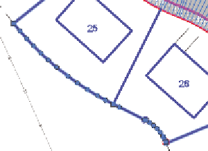
When prompted to specify the start point, click the west corner of lot
25, and then click the south corner of lot 26 to specify the endpoint.
A series of green circle
markers appears on the
feature line.
15.
Press Enter to complete the command.
A number of circular grips are now visible on the feature line
(see Figure 17.7). These represent additional elevation points that
were required for the feature line to match the surface precisely.
FiGuRE 17.7
Circular grips mark
elevation points added to match the feature
line to the surface.
16.
Save and close the drawing.
You can view the results of successfully completing this exercise by opening
Editing Feature Line Elevations - Complete.dwg
.
understanding Grading objects
At times, you'll want Civil 3D to calculate the location, shape, and elevations
of feature lines rather than designing them yourself. Examples of this situation
would be projecting a slope through a certain distance or elevation or finding
the intersection of a slope with a surface. For these cases, Civil 3D provides the
grading object
. Figure 17.8 shows a pond design composed of several grading
objects, each one using a different set of parameters to calculate an edge that
defines the shape of the pond.
A
grading object
is a collection of feature lines whose geometry, location, and
elevation are calculated by Civil 3D based on design parameters that you have
applied to a feature line. That's quite a daunting definition, so here's a look at it
broken down into several parts:
▶
A grading object is a
collection
of feature lines (and other things not
important to name at this time), so it behaves as one object. The fea-
ture lines in this collection have many of the same characteristics as