Graphics Programs Reference
In-Depth Information
▶
6.
In the Pick Pipe Style dialog box, select C-PROF-STRM - Crossing and
click OK. Click OK once more to dismiss the Profile View Properties
dialog box.
You're returned to the drawing, and the storm pipe is now repre-
sented as an ellipse. The ellipse is placed at the location where the
storm pipe crosses the alignment (see Figure 16.6).
When you view the
storm and sanitary
pipes this way, you can
clearly see that there is
a conflict and that you
need to change
the design.
7.
Save and close the drawing.
You can view the results of successfully completing this exercise by
opening
Applying Pipe Styles - Complete.dwg
.
Storm Pipe Crossing
FiGuRE 16.6
A storm pipe crossing shown as an ellipse indicates a
conflict with a sanitary pipe.
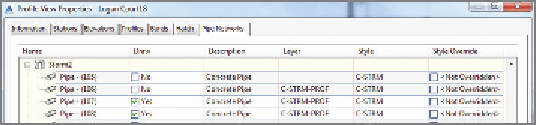
Profile view overrides
The Profile View Properties dialog box has a special Pipe Networks tab that lists
all the pipes and structures in the drawing. You can display any of them in a given
profile view by simply checking a box in the Draw column. You can even perform
a style override so that a pipe or structure can be displayed in a given profile
view using a different style than the one assigned to it in the Pipe Properties
dialog box. This is especially handy when you need to show a pipe using a crossing
style in one profile view and using a “normal” style in another. The following
image shows the Pipe Networks tab of the Profile View Properties dialog box.