Graphics Programs Reference
In-Depth Information
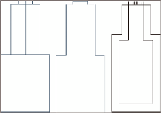
FiGuRE 16.2
A structure shown as a
solid (left), boundary (center), and block (right)
Block
A block (see Figure 16.2, right) is inserted and sized based on one of sev-
eral options. The most common option is to scale the block vertically to match the
height of the part and horizontally to match the width of the part. A block can pro-
vide the desired appearance of the part, but because of the horizontal and vertical
scaling, it may not be an exact dimensional match to the actual part.
For fittings and appurtenances, the plan view choices are Centerline, Catalog
Defined Block, and User Defined Block:
Centerline
Centerline (see Figure 16.3, left) is the simplest choice, which
represents the fitting or appurtenance as a single line.
FiGuRE 16.3
A tee fitting shown as a centerline (left), catalog
defined block (center), and user-defined block (right).
Catalog Defined Block
Catalog Defined Block (see Figure 16.3, center) is the
true 3D form of the fitting or appurtenance shown in plan view.
user Defined Block
The User Defined Block (see Figure 16.3, right) option
allows you to use any AutoCAD block to represent the fitting or appurtenance.
In profile view, there are no options for the display of fittings and appurte-
nances; fittings are simply represented as an outline, and appurtenances are
represented by a symbol that resembles their type.