Graphics Programs Reference
In-Depth Information
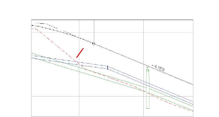
FiGuRE 15.4
Pressure network parts (indicated with red arrows)
shown in profile view along with other profile information
You can view the results of successfully completing this exercise by opening
Creating Pressure Networks from Objects - Complete.dwg
.
Pressure Networks from Feature lines
You may have noticed the Use Vertex Elevations option in the Create Pressure Pipe
Network From Object dialog box. If you create a pressure network from a feature
line, you can use this option to set the elevations of the pipes and fittings based
on the elevations of the feature line. You can also choose the reference point
that is used when assigning elevations such as Outside, Top, Crown, Centerline,
and so on. This is an effective way to convert a rough 3D sketch of a pressure
pipe design into a full-fledged 3D pressure network model.
Creating a Pressure Network by layout
Another way to create pressure networks is using the Pressure Network Creation
Tools command. When you launch this command, a specialized ribbon tab (see
Figure 15.3) opens that contains tools for pressure network layout. From this spe-
cialized ribbon tab, you can choose the pipes, fittings, and appurtenances from the
parts list and use the commands on the ribbon to insert those parts into the draw-
ing. You can change parts at any time and apply different types and sizes as you go.
To guide your design, Civil 3D provides a
compass
(see Figure 15.5), which
displays the bend angles and deflections available at a given point, based on
information stored in the parts list. The compass automatically “snaps” your