Graphics Programs Reference
In-Depth Information
For this reason, elevations aren't nearly as important to ensure adequate flow. They
are important, however, to ensure that the pipeline has adequate cover to prevent
freezing or physical damage and that it avoids underground obstacles, including
other pipes. In the event of a conflict, because pressure pipe flow isn't dependent
on elevation, a designer will typically bend a pressure pipe to avoid a gravity pipe
rather than the other way around. As discussed previously, the required bends are
a design challenge because of the available fittings and deflection angles.
Exploring the Pressure Network
Civil 3D enables you to create objects that represent fittings, pipes, and appur-
tenances. It also establishes relationships between these components as well as
relationships with other important design elements such as surfaces, alignments,
profiles, and profile views. The pipes, fittings, and appurtenances and their associ-
ated relationships are referred to as a Civil 3D
pressure network
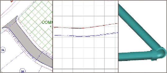
. In Figure 15.1, a
few pipes and fittings are show in plan view on the left, profile view in the center,
and 3D view on the right.
Each component of a pressure network is shown in Prospector beneath the
Pressure Networks node. From here, you can right-click each component to
access various context commands for it. You can also use the item view at the
bottom of Prospector to edit information about each component. Figure 15.2
shows the contents of a pressure network in Prospector.
Just as in gravity networks, the shape, dimensions, and behavior of a pres-
sure network component are determined by the
part
that represents it. Pressure
networks have their own parts lists, separate from gravity networks. Most com-
panies have several parts lists, each one containing parts for a certain type of
system such as water, sanitary, or natural gas.
FiGuRE 15.1
A pressure network shown in plan view (left), profile
view (center), and model view (right)