Graphics Programs Reference
In-Depth Information
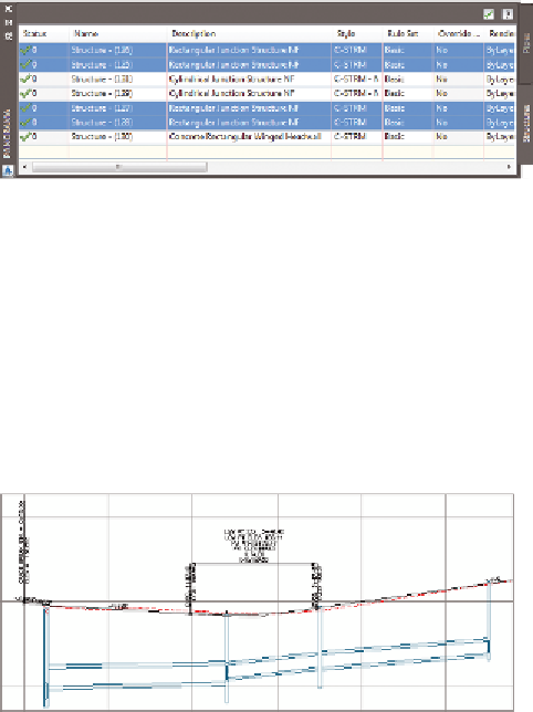
FiGuRE 14.16
Selecting multiple rows in the Structures tab
of Panorama
9.
Click the Pipes tab. While holding down the Shift key, click the first
and last rows. All rows should now be selected.
10.
Right-click the Style column, and select Edit. In the Select Pipe Style
dialog box, select C-STRM - Walls In Profile. Click OK.
The appearance of the pipes in profile view changes so that the
inside and outside pipe walls are shown (see Figure 14.17).
FiGuRE 14.17
Pipes in profile view shown with inside and
outside walls
11.
Save and close the drawing.
You can view the results of successfully completing this exercise by opening
Editing Pipe Networks Using the Pipe Network Vistas - Complete.dwg.
Now You Know
Now that you have completed this chapter, you're ready to begin creating and modifying gravity
pipe networks. You can create these networks from objects in the drawing or by drawing them
yourself using the Network Layout Tools toolbar. Once you have created a network, you can display
it in profile view and edit it using grips, editing tools, properties, and the Pipe Network Vistas.
You're ready to begin working with gravity pipe networks in a production environment.