Graphics Programs Reference
In-Depth Information
4.
If your Osnap icon is turned on, click it to turn it off.
▶
5.
In either the plan viewport or the 3D viewport, click near the midpoint
of the pipe that begins at station 2+40.42 (0+073.280) and ends at
station 5+50 (0+170).
A new manhole is
inserted along the pipe.
6.
Press Esc to clear the current command. Click the newly created
structure, and then click the square grip at its center.
7.
Snap to the center of the red circle located near Jordan Court
station 3+50 (0+110).
8.
Press Esc to clear the previous selection. In the left viewport, click
the pipe that enters the new manhole from the south. Click Swap
Part on the ribbon.
9.
In the Swap Part Size dialog box, click Concrete Pipe (SI)
➢
18 Inch
(450mm) Concrete Pipe and then click OK.
10.
Repeat steps 8 and 9 for the pipe that exits the new manhole to
the north.
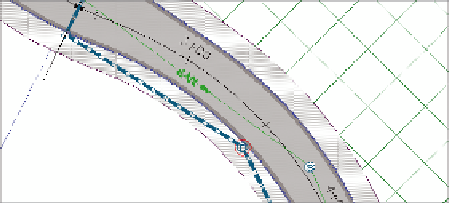
You have now inserted a new manhole and resized the pipes that
connect to it (see Figure 14.13).
11.
Close the Network Layout Tools toolbar, and press Esc to clear the
previous selection. Click one of the sanitary sewer pipes in the draw-
ing, and then click Merge Networks on the ribbon.
Here, you're selecting
a network that will be
merged into another.
When the process is
complete, a network
of this name will no
longer exist.
New Manhole
FiGuRE 14.13
Newly created manhole and resized connecting pipes
▶
▶
12.
In the first dialog box, click Sanitary-2 and then click OK.
13.
In the second dialog box, click Sanitary and then click OK.
14.
In Prospector, expand Pipe Networks
➢
Networks. Note that the
Sanitary-2 network is no longer listed.
Here, you're select-
ing the network that
is having Sanitary-2
merged into it..