Graphics Programs Reference
In-Depth Information
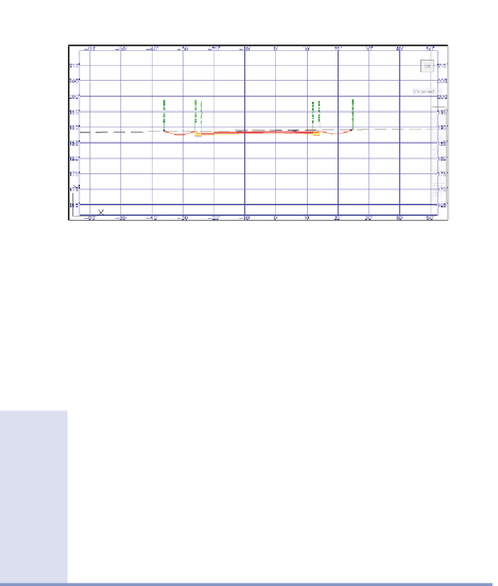
Notice the line
markers that indicate
your location in plan
and profile view.
FiGuRE 10.2
A section view shown by the Section Editor command
3.
In the left viewport, zoom out until you can see the plan view of the
site as well as the Jordan Court profile view. On the ribbon, click the Go
To Next Station icon to advance to the next corridor section. Continue
advancing to view several different corridor sections.
◀
What's in a Name?
Think back to the previous chapter when you spent some time in Exercise 9.3
renaming the individual subassemblies that made up the composition of the
road. You should recognize the names Left Daylight and Right Daylight here
in Exercise 10.1. This is an example of how spending a few extra seconds on
bookkeeping helps things go much more smoothly when you're further along
in the design process. It's an even bigger help when you're working on a team;
your teammates will thank you when your good bookkeeping makes their jobs
easier and saves them time.
These were added
automatically because
the road is in a cut
condition; however,
the amount of cut is so
small that the ditches
can be omitted, a
change you'll make in
the next few steps.
◀
4.
On the ribbon, expand the list under Select A Station, and select
1+75.00' (0+050.00 m). Zoom in to the section view, and note the
ditches on either side of the road.
◀
5.
Click Parameter Editor on the ribbon. This opens the Corridor
Parameters window.
These two values define
the width of the ditch.
When you set them
to zero, the ditch will
disappear.
6.
In the Corridor Parameters window, scroll down to Left Daylight and
change the value for Backslope Width and Foreslope Width to
0.000
.
Repeat for the Right Daylight subassembly.