Graphics Programs Reference
In-Depth Information
6.
Press Esc twice to clear the selection of the profile view and end the
command. Then click the newly created label, and drag the square
grip up and to the right.
◀
7.
With the label still selected, click Edit Label Text on the ribbon.
8.
In the text view window on the right, click just to the left of STA to
place your cursor at that location. Press Enter to move that line of
text down and provide a blank line to type on.
This opens the Text
Component Editor.
9.
Click the blank line at the top, type
TIE TO EDGE
, and press Enter.
10.
Type
OF EXIST ROAD
.
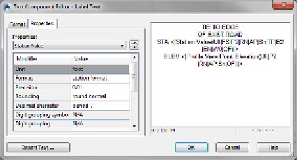
The Text Component Editor dialog box should now look like
Figure 8.9.
Nearly all Civil 3D
labels can be edited
in this way.
11.
Click OK to return to the drawing.
The label now clearly calls out the station and elevation where the
new road should tie to the existing road.
◀
FiGuRE 8.9
Additional text added to a label in the
Text Component Editor dialog box
12.
Press Esc to clear the current label selection. Click one of the grid
lines of the profile view, and then click Add View Labels
➢
Depth.
◀
13.
Pick a point at the invert of the V-shaped ditch, and then pick a point
just above it approximating the top of the ditch.
Invert
is a term referring
to the lowest elevation
of the ditch. It's also
used to refer to the low-
est elevation of a pipe
or a structure, such as a
manhole or inlet.
14.
Press Esc twice to end the command and clear the selection of the
profile view.
15.
Click the newly created depth label, and then click one of the grips at
the tip of either arrow. Move the grip to a new location, and note the
change to the depth value displayed in the label.