Graphics Programs Reference
In-Depth Information
7.
Save and close the drawing.
You can view the results of successfully completing this exercise by
opening
Profile View Style - Complete.dwg
.
Applying Profile view Bands
If you haven't already
done so, download
and install the files for
Chapter 8 according to
the instructions in the
Introduction.
Profile view bands can be added to a profile view along the top or bottom axis.
You can use these bands to provide additional textual or graphical informa-
tion about a profile. They can be configured to provide this information at even
increments or at specific locations along the profile.
Exercise 8.3: Apply Profile view Bands
In this exercise, you'll configure bands for the Jordan Court profile view so that
information about stations, elevations, and horizontal geometry can be displayed.
▶
1.
Open the drawing named
Profile View Bands.dwg
located in the
Chapter 08
class data folder.
Earlier, you used the
AutoCAD
®
Properties
window to change the
profile view style. This
is another way to do it.
2.
Click one of the grid lines of the Jordan Court profile view, and then
click Profile View Properties on the contextual ribbon tab.
▶
3.
On the Information tab of the Profile View Properties dialog box,
change Object Style to Major & Minor Grids 10V.
4.
Click the Bands tab. Verify that Profile Data is selected as Band Type.
5.
Under Select Band Style, choose Elevations And Stations. Then
click Add.
▶
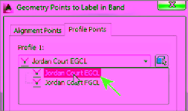
6.
In the Geometry Points To Label In Band dialog box, on the Profile
Points tab, select Jordan Court EGCL as Profile 1, as shown in
Figure 8.4. Click OK.
A new entry is added to the list of bands.
You may have noticed
the long list of geome-
try points in this dialog
box. The band style you
have selected doesn't
include references to
any of these points;
therefore, no geometry
point information will
appear on the band.
FiGuRE 8.4
Assigning Jordan Court EGCL as Profile 1