Graphics Programs Reference
In-Depth Information
5.
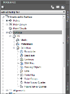
In Prospector, expand Surfaces
➢
EG
➢
Definition. Study the items
listed beneath EG in the tree (see Figure 4.3).
The difference in
appearance between
plan view and 3D view
is a function of the
surface style.
FiGuRE 4.3
The contents
of a surface shown in Prospector
6.
Right-click Point Groups, and select Add.
▶
7.
Select Ground Shots, and click OK. The surface is now visible in plan
view in the form of contours and shaded 3D faces in the bottom-right
3D view.
8.
In the lower-right viewport, click Shaded and select 2D Wireframe, as
shown in Figure 4.4. The appearance of the surface changes to show
the TIN lines.
This way of studying
the surface gives a real
sense of the surface as a
“solid” model in which
the area inside the
triangles has substance.
It's also a great visual
representation of the
TIN algorithm and the
surface model (see
Figure 4.5).
FiGuRE 4.4
Changing the visual
style to 2D Wireframe in the lower-right
viewport
▶
9.
Click 2D Wireframe and select Conceptual. To orbit your view of the
surface, click and drag center mouse button while holding your Shift
key. Observe the surface from several different viewpoints.
10.
Save and close the drawing.
You can view the results of successfully completing this exercise by
opening
Create an EG Surface - Complete.dwg
.