Geology Reference
In-Depth Information
within the reservoir units. Current and future work re-
quires that multidisciplinary data, analytical techniques
and interpretations be integrated. This includes outcrop
studies of field analogs, seismic modeling, wireline log
modeling, geochemical stratigraphy, geomechanical
and special core analysis. The description and quanti-
fication of reservoir heterogeneities
require integrat-
ing depositional, diagenetic, and petrophysical model-
ing at various scales.
agenesis are recorded by microfacies criteria. Basic dif-
ferentiation of textural carbonate types requires thin-
section studies. Thin sections are the key to understand-
ing the geometry of major pore types and distinguish-
ing effective from ineffective porosity.
Today integrating qualitative and quantitative micro-
facies data, analog studies, petrographic core analysis,
seismic analysis and high-resolution reservoir-scale
correlation, and 3D modeling form the basis for the
characterization of carbonate fields (Grötsch et al. 1998;
Grötsch and Mercadier 1999; Grötsch et al. 2003).
The currently most challenging hurdle in modeling
carbonate hydrocarbon reservoirs is the linkage be-
tween the static reservoir description and the dynamic
model. With recent advances made in dynamic model
resolution (>1 million cells), the question of how to
add dynamic rock properties as measured by special
core analysis (e.g. drainage-inbibition capillary mea-
sure, relative permeability) to each model cell in a
consistant fashion became of crucial importance
(Grötsch et al. 2003). An example is the Kharaib For-
mation in the Middle East where a strong increase in
permeability towards the top of the formation results
in water overriding oil over large distances despite the
presence of gravitational forces (Grötsch et al. 1998).
What place does microfacies have?
Carbonate res-
ervoirs should be investigated at all scales. Reservoir
studies need an understanding of large-scale deposi-
tional environments and geometrical patterns and me-
dium- to small-scale variations in lithology, depositional
facies and diagenetic overprints responsible for the het-
erogeneity of petrophysical properties of carbonate res-
ervoirs. Depositional environments are evaluated from
the sedimentological and palecological criteria reflected
by microfacies criteria. Carbonate geometries and cy-
clic depositional changes are analyzed by high-resolu-
tion sequence stratigraphy. Outcrop analog studies ex-
hibit size, internal architecture, composition and diage-
netic history of carbonate bodies. Composition and di-
17.1.1 Distribution of Carbonate Reservoirs
during Time
Number of
carbonate reservoirs
Carbonate reservoirs are known from the Precambrian
and all through the Phanerozoic, but are concentrated
within several intervals (Greenlee and Lehman 1993;
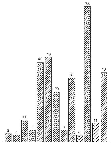
Kiessling et al. 1999; Kiessling 2002). Fig. 17.1 shows
the temporal distribution of carbonate reservoirs located
in various depositional settings (see Fig. 17.3). Fig. 17.2
is limited to reef carbonates with reservoir quality. The
principal times of reef reservoirs agree approximately
with the maximum reef expansion. Both figures dem-
onstrate a conspicuous heterogeneous distribution, dis-
tinct peaks and times with rare reservoirs. Peaks occur
in the Late Devonian, Late Carboniferous and Early
Permian, Late Jurassic, Mid-Cretaceous and Miocene.
PC COS DC P T
J
K
TT
17.1.2 Depositional Setting and Environ-
mental Controls of Carbonate Reservoirs
Fig. 17.1.
Temporal distribution of carbonate reservoirs.
Age
of 330 carbonate reservoirs all over the world studied by C
& C Reservoirs, Inc.. Reservoirs occur in all time intervals
but are abundant in the Devonian, Late Paleozoic, Jurassic,
Cretaceous and Tertiary. Note that the height of the columns
does not reflect the relative abundance, but rather the gen-
eral pattern. Based on internet data (www. ccreservoirs.com).
17.1.2.1 Depositional Setting
The distribution of primary porosity is strongly facies-
controlled as illustrated by the Great Bahama Bank
model (Sect. 7.4.4; Fig. 7.13). Local facies variations