Biomedical Engineering Reference
In-Depth Information
the observed spectral peaks, it is usually possible to determine the presence of neutral and ionic spe-
cies. The relative concentrations of species can be obtained by correlating changes in the intensity
with the plasma parameter changes.
19.2
PLASMA IMMERSION ION IMPLANTATION AND DEPOSITION
19.2.1 C
ONCEPTS
AND
F
UNDAMENTALS
OF
PIII
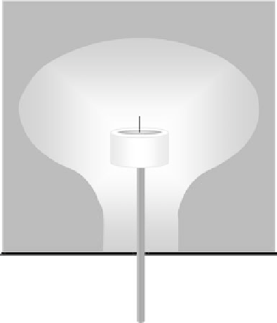
Generally, a plasma immersion ion implantation (PIII) system consists of a vacuum chamber with
a workpiece stage, plasma source, and high-voltage pulse modulator as shown in Figure 19.5. In the
PIII process, a workpiece is immersed in plasma and pulsed to a high negative voltage with respect
to the plasma potential, which is usually close to the ground potential of the chamber walls. The
applied high voltage accelerates electrons away from the workpiece while accelerating the positive
ions from the source plasma toward the workpiece, creating a plasma sheath around the workpiece
and implanting the ions [11].
In the initial stage when the negative voltage is applied to the target, electrons are repelled on
the time scale of the inverse electron plasma frequency to establish a positive space-charged region,
and the potential profi le can be described by the ion matrix sheath. Followed by ion collection or
extraction and plasma sheath expansion, a quasistatic Child-Law sheath evolves. The evolution of
the plasma sheath plays a very important role in PIII because it dictates the implantation process and
can be used to predict process parameters and results including the implantation current, implanta-
tion dose, and impurities profi le. Positive ions are accelerated by the electric fi eld and implanted
into the substrate with near-Gaussian depth distribution of which the projected range can be esti-
mated by the TRIM simulation codes [12]. As implantation takes place on all exposed and biased
surfaces, PIII can be a conformal treatment process for irregular targets, and the implantation time
RF-ICP
Gas
inlet
Wafer
High-voltage
pulsed power
source
Vacuum
pump
FIGURE 19.5
Schematic diagram of PIII system.