Biomedical Engineering Reference
In-Depth Information
WE well to produce the round T-shape with rough surface discussed above. It was experimentally
determined that electroplated Au posts need to be at least 8-9 µm high to provide good mechanical
support for the PPy. The photoresist is then stripped away using oxygen plasma etching, and the
chip is ready for electropolymerization of PPy. An aqueous solution of 0.04 M pyrrole and 0.04 M
NaDBS is prepared, and the PPy is deposited onto the WE at 0.62 V (versus Ag/AgCl CE) using
a potentiostat. Polymerization time is 4.3 h, resulting in a PPy(DBS) thickness of 34 µm on top of
the gold post. PPy grows laterally as well, at roughly the same rate, producing a pattern width of
around 110 µm (gold post width is 40 µm and has
35 µm of PPy surrounding it). This growth is
not uniform, and the resulting pattern is not symmetrical. Rather, it appears that PPy growth follows
slight imperfections in the substrate surface.
∼
13.3.2.2
Microfabrication of the Passive Microfl uidic Component
A technique known as soft lithography was utilized in the fabrication of PDMS microchannels.
Briefl y, the working channel was made by photolithographically defi ning a positive photoresist of
6.2 µm thickness into 50 µm wide and 20 mm long strips making a Y-shape on silicon substrate.
The photoresist was then refl owed at 150°C for 20 min, producing a spherical cross-section (the
resist cross-section was originally rectangular, see Figure 13.16D). A prepolymer of PDMS was
then mixed with a cross-linking agent, degassed in vacuum, and poured onto the silicon wafer with
photoresist pattern. After a curing step, the fully cross-linked PDMS was peeled off the silicon
mold master by hand, and cut into chip-sized pieces.
Fluid inlet A
Working electrode
Polypyrrole microactuator
B
C
Counter electrode
Fluid outlet B
Electrolyte
bath
A
Fluid inlet B
D
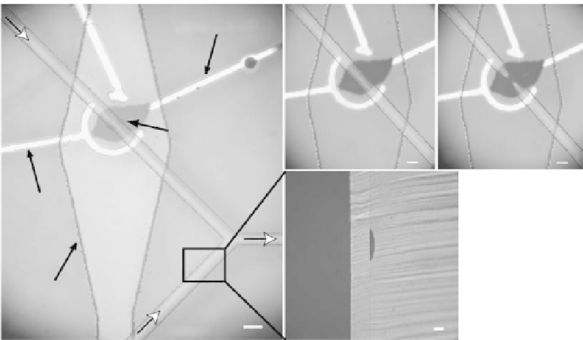
FIGURE 13.16
Micrograph of the top view of the fully assembled microvalve including the active compo-
nent with electrodes and metal traces (bright lines), rhombus-shaped electrolyte bath, and Y-shaped working
channel (A). The valve is placed under one of the arms of the Y, preventing or allowing the analytes fl owing
in that channel from merging with contents of the other arm. (B) Valve is open. (C) Valve is closed. Expand-
ing polypyrrole (dark material between Au traces) can be seen to pinch off the working channel in (C). The
bar represents a distance of 50 µm. (D) The cross-section of the working microfl uidic channel molded against
refl owed photoresist and sealed with PDMS membrane. Bar represents a distance of 50 µm in (A)-(C) and a
distance of 15 µm in (D).