Biomedical Engineering Reference
In-Depth Information
to the capacitive charging of the double layer throughout the polymer (which can be viewed as a
conductive porous electrode), the contribution of electric fi eld-driven ion migration
9
to the apparent
diffusion constants of Na
+
ions and their water solvation shells, and the uncompensated solution
resistance between the electrodes in the electrochemical cell, which can introduce a signifi cant
voltage drop and effectively lower the applied voltage at the fi lm-solution interface. A theoretical
analysis of the diffusion contribution to the time course of PPy doping/undoping is discussed in
Section 13.4 in which the role of PPy device geometry (shape and size) in the electrochemical time
response is examined.
13.2.3 A
CTUATION
OF
P
OLYPYRROLE
M
ICROSTRUCTURES
13.2.3.1
Microfabrication of the Polypyrrole Test Lines
To evaluate the ability of PPy microstructures to function as actuators due to electrochemi-
cally induced changes in thickness, PPy micro-test lines of varying width were fabricated using
photolithographic techniques and tested in solution using a profi lometer and an optical microscope.
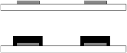
The fabrication sequence is shown schematically in Figure 13.7.
Voltage of 0.55 V versus Ag/AgCl was applied to all Au/Ti lines simultaneously for 7 h to
produce a fi lm of 6.5-7 µm thickness coating the metal (Figure 13.8). Since PPy growth occurs
isotropically, a widening of the Au/Ti patterns occurred. The thickness was uniform over the
metal except the edges, where the PPy coating was thicker by approximately 1 µm than in the
middle of the metal strip line. This edge thickness is caused by nonuniformity in the electric fi eld
and the improved pyrrole monomer diffusion at the edges of the metal lines, which act as WEs.
13.2.3.2 Measurement of Electrochemically Controlled
Thickness Change of Polypyrrole Test Lines
Experimental setup for the evaluation of electrochemically induced thickness changes in the PPy
test lines is shown schematically in Figure 13.9.
Two methods were used to evaluate the thickness changes of the PPy test lines induced by
applied voltage: a mechanical profi lometer measurement and optical imaging. The profi lometer
has the advantage of higher sensitivity and precision, but due to the physical constraints of the
equipment used, a very shallow electrolyte bath was used. A gold CE had to be fabricated on
the same substrate as WE, while REF was excluded. Therefore, the voltage was applied between
A
Clean glass substrate
B
Ti/Au sputtering
Glass substrate
Ti /Au film
Photoresist
Polypyrrole
C
Photolithography
D
Au/Ti / Ti etching
E
Removal of photoresist
Polypyrrole electropolymerization
F
FIGURE 13.7
Steps for the microfabrication of polypyrrole test lines.


