Biomedical Engineering Reference
In-Depth Information
Electrospray ionization module
Nanomaterial assembly module
Orifice plate
Lens
Charge neutralizer
+V
DC
A
CO
2
/air flow
Air filter
Electrometers
V
DC
Capillary
−
A
V
DC
External
electric field
A
+V
DC
HV
N
2
N
2
N
2
A
N
2
N
2
Electrometer
V
DC
Particles in
conductive
solution
−
Charged area
A
Drop neutralization
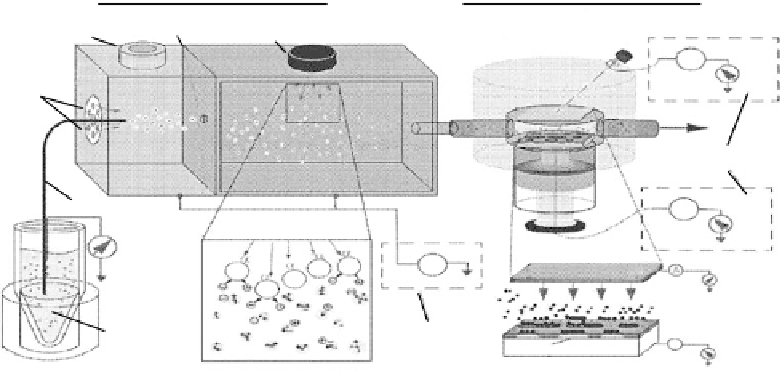
FIGURE 11.35
A schematic diagram of electrospraying technique for controllable deposition. (Reprinted
from Welle, A.M. and Jacobs, H.O.,
Appl. Phys. Lett.
, 87, 263119, 2005. © American Institute of Physics. With
permission.)
(c)
(a)
(b)
200
µ
m
200
µ
m
2
µ
m
2
µ
m
2
µ
m
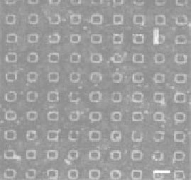
FIGURE 11.36
Fluorescent microscope images
of printed proteins are as follows: (a) albumin FITC bovine,
(b) avidin sulforhodamine, and (c) albumin FITC bovine. (Reprinted from Welle, A.M. and Jacobs, H.O.,
Appl. Phys. Lett.
, 87, 263119, 2005. © American Institute of Physics. With permission.)
assembly module. The electrospraying system, which consisted of a high-voltage source, a pressure
regulator and chamber, a capillary, and a neutralization chamber, can provide a greater control
to monitor the electrospraying currents. An electrometer was used to monitor the electrospraying
current, which varied depending on
the fl ow rate, the solution properties, and the electrospraying
voltage. The highly charged primary droplets entered a neutralization chamber and formed aerosol,
which was introduced to an assembly module through an opening. An electric fi eld was applied to
bring charged biological materials into close proximity of the charged patterned substrate to attract
the oppositely charged biomaterials in an assembled way. Figure 11.36 shows fl uorescent micro-
graphs taken from different types of proteins deposited on substrates using electrospraying. All
images show patterned microstructures generated through a controlled deposition. Figure 11.36a
shows albumin fl uorescein isothiocyanate (FITC) bovine deposited onto negatively charged lines.
The albumin FITC bovine was electrosprayed in a positive ion mode to generate positively charged
protein aerosol, and then a positive potential was applied to the top electrode in the assembly mod-
ule while the
substrate was kept at ground to direct the positively charged
proteins to the substrate