Biomedical Engineering Reference
In-Depth Information
Stainless steel capillary
Copper
electrode
Infusion pump
Syringe
+++++
DC voltage
Copper
electrode
−−−−−
Power supply
0
−
3000 V
Collecting tube
FIGURE 11.14
A schematic representation of electrospraying equipment. (Reprinted from Reyderman, L.
and Stavchansky, S.,
Int. J. Pharm.
, 124, 75, 1995. © Elsevier Science. With permission.)
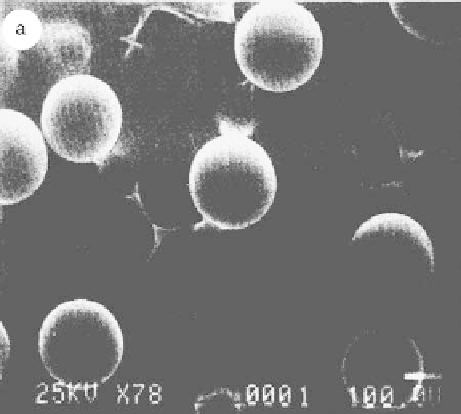
FIGURE 11.15
SEM of cholesterol microspheres prepared using electrospraying. (Reprinted from
Reyderman, L. and Stavchansky, S.,
Int. J. Pharm.
, 124, 75, 1995. © Elsevier Science. With permission.)
release formulation upon intramuscular or intradermal administration. A schematic diagram of the
apparatus used in the work is shown in Figure 11.14. The apparatus consisted of an infusion pump, a
glass syringe, a stainless steel capillary, and a power supply. The electrodes were positioned 0.2 cm
apart, one of them being at the tip of the capillary. A heating mantle controlled by a thermostat
was positioned around the syringe extending down to the capillary and upper electrode to main-
tain cholesterol in the molten state and to provide uniform fl ow for electrospraying cholesterol in a
molten state. SEM image revealed that the cholesterol microspheres prepared using a 3 kV voltage
source had a mixture of spherical particles of 150-250 µm, as shown in Figure 11.15. The experi-
ments demonstrated that electrospraying has another potential use in spraying a melt for producing
microspheres in a uniform size. However, considerations need to be placed on the thermal stability