Biomedical Engineering Reference
In-Depth Information
(
4
k
2
r
jet
n
I
′
m
(
kr
jet
)
-
I
′
-
m
(
kr
jet
)
[
{
)
}
]
lim
__________
(8
m
_________________
=
k
2
r
jet
)
1
-
k
2
r
jet
-
2
R
Es
1
+
kr
jet
I
-
m
(
kr
jet
)
(11.28)
→
I
m
(
kr
jet
)
-
+
1.5
ρ
0.5
ωr
jet
σ
2
r
jet
µ
_______
________
____
ω
′
=
γ
0.5
; Oh
=
(
γρd
jet
)
1/2
;
k
′
=
kr
jet
;
R
Es
=
2
γε
0
(11.29)
where
µ
is the absolute liquid viscosity,
ρ
the liquid density, and
I
m
is a Bessel function.
The Oh
is a ratio of loss of energy resulting from viscosity over the potential energy of the jet
because of surface tension,
k
the ratio of the jet radius over the wavelength times 2
π
, and
R
Es
is
the ratio of the electric stress over the surface tension stress. The normalized growth rate
ω
′
can be
calculated as a function of the dimensionless numbers of Equation 11.29 by using Equation 11.28.
′
11.2.6 B
ASIC
E
LECTROSPRAYING
S
YSTEM
In a typical instrumental setup, the electrospraying is generated by pumping liquid into a conduc-
tive capillary at a high potential relative to a grounded surface. When the liquid emerges from the
capillary, the droplet is distorted by a strong electrical fi eld and forms a conical spraying mode
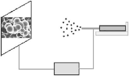
commonly known as a Taylor cone. Figure 11.8 shows basically the experimental setup, which is
composed of a capillary, a high-voltage power supply, a syringe pump, and a collector. The solution
is forced from a syringe reservoir by a syringe pump through a plastic tube attached to the capillary,
which can be designed to have different outer and inner diameters. The fl ow rate of the solution can
be controlled through a programmable syringe pump. The capillary is maintained at a high poten-
tial by connecting it to a high-voltage power supply. The strength of the electric fi eld and its patterns
can be generated and controlled using a programmable high-voltage power supply. A collector, held
a specifi ed distance from the capillary, is either grounded or negatively charged. In some cases, to
obtain the spraying patterns and the dynamic behaviors of electrosprayed droplets under an applied
electric fi eld, the electrospraying process can be monitored through a controlling system, which
consists of a high-speed charge-coupled device (CCD) camera with a magnifying lens, a synchro-
nized strobe lamp, and an integrated frame-grabber or image-processor.
11.2.7 C
HARACTERISTICS
OF
E
LECTROSPRAYING
Experiments have demonstrated electrospraying to be capable of generating micro- or nanometer
droplets. These highly charged droplets result in self-repelled particles without coalescence. By
selecting the proper processing parameters, the electrosprayed droplets can be produced in a nar-
row size distribution. It is conceptually easy to control the size of electrosprayed particles from
nanometer to micrometer by varying the fl ow rate of the solution, the applied voltage, the spraying
Collector
Syringe
Nozzle
Syringe pump
V
Power supply
FIGURE 11.8
A basic electrospraying setup.