Hardware Reference
In-Depth Information
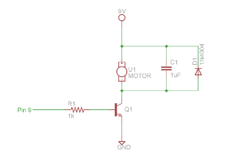
Figure 4-1:
DC motor control schematic
Before you hook up your DC motor, it's important to understand what all
these components are doing:
■
Q1 is an NPN bipolar-junction transistor (BJT) used for switching the
separate 9V supply to the motor. There are two types of BJTs, NPN and
PNP, which refer to the different semiconductor “doping” techniques
used to create the transistor. This topic will focus on using NPN BJTs.
You can simplistically think of an NPN transistor as a voltage-controlled
switch that allows you to inhibit or allow current flow.
■
A 1kΩ resistor is used to separate the transistor's base pin from the control
pin of the Arduino.
■
U1 is the DC motor.
■
C1 is for filtering noise caused by the motor.
■
D1 is a diode used to protect the power supply from reverse voltage
caused by the motor acting like an inductor.
Using Transistors as Switches
Transistors can do an exceptional number of tasks, from making amplifiers to
making up the CPU inside your computer and smartphone. You can use a single
Search WWH ::

Custom Search