Hardware Reference
In-Depth Information
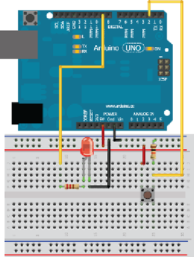
all digital inputs use a pullup or pulldown resistor to set the “default state” of
the input pin. Imagine the circuit in Figure 2-5 without the 10kΩ resistor. In this
scenario, the pin would obviously read a high value when the button is pressed.
But, what happens when the button is not being pressed? In that scenario, the
input pin you would be reading is essentially connected to nothing—the input
pin is said to be “floating.” And because the pin is not physically connected to
0V or 5V, reading it could cause unexpected results as electrical noise on nearby
pins causes its value to fluctuate between high and low. To remedy this, the
pulldown resistor is installed as shown in Figure 2-5.
Now, consider what happens when the button is not pressed with the pull-
down resistor in the circuit: The input pin will be connected through a 10kΩ
resistor to ground. While the resistor will restrict the flow of current, there
is still enough current low to ensure that the input pin will read a low logic
value. 10kΩ is a fairly common pulldown resistor value. Larger values are said
to be
weak pulldowns
because it easier to overcome them, and smaller resistor
values are said to be
strong pulldowns
because it is easier for more current to flow
through them to ground. When the button is pressed, the input pin is directly
connected to 5V through the button.
Now, the current has two options:
■
It can flow through a nearly zero resistance path to the 5V rail.
■
It can flow through a high resistance path to the ground rail.
Figure 2-5:
Wiring an Arduino to a button and an LED

Search WWH ::

Custom Search