Hardware Reference
In-Depth Information
Wiring LEDs
LEDs will almost certainly be one of the most-used parts in your projects through-
out this topic. LEDs are polarized; in other words, it matters in what direction
you hook them up. The positive lead is called the
anode
, and the negative lead
is called the
cathode
. If you look at the clear top of the LED, there will usually
be a flat side on the lip of the casing. That side is the cathode. Another way to
determine which side is the anode and which is the cathode is by examining
the leads. The shorter lead is the cathode.
As you probably already know, LED stands for light-emitting diode. Like all
diodes, LEDs allow current to flow in only one direction—from their anode to
their cathode. Because current flows from positive to negative, the anode of the
LED should be connected to the current source (a 5V digital signal in this case),
and the cathode should be connected to ground. The resistor can be inserted in
series on either side of the LED. Resistors are not polarized, and so you do not
have to worry about their orientation.
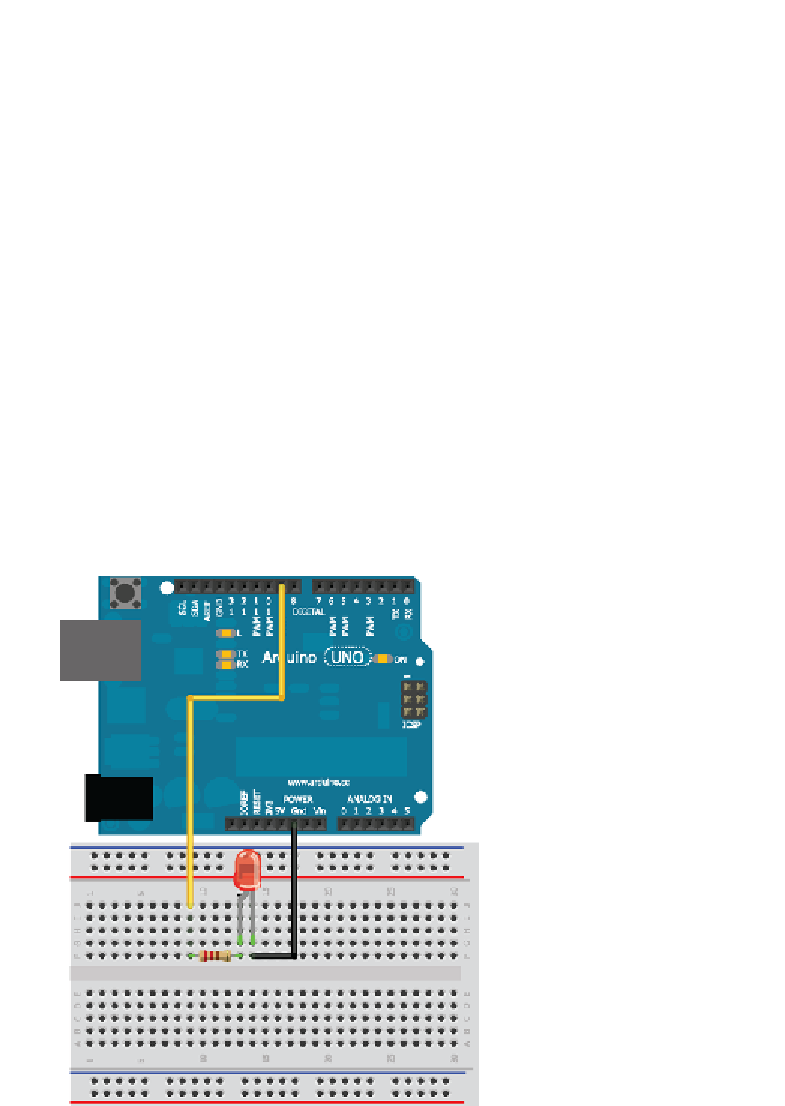
You'll wire the LED into pin 9 in series with a resistor. LEDs must always be
wired in series with a resistor to serve as a current limiter. The larger the resistor
value, the more it restricts the flow of current and the dimmer the LED glows.
In this scenario, you use a 220Ω resistor. Wire it up as shown in Figure 2-2.
Figure 2-2:
Arduino Uno wired to an LED
Search WWH ::

Custom Search