Hardware Reference
In-Depth Information
the coming chapters. What's more, pin 9 is PWM-enabled, which will enable
you to pursue the analog output examples later in this chapter.
Working with Breadboards
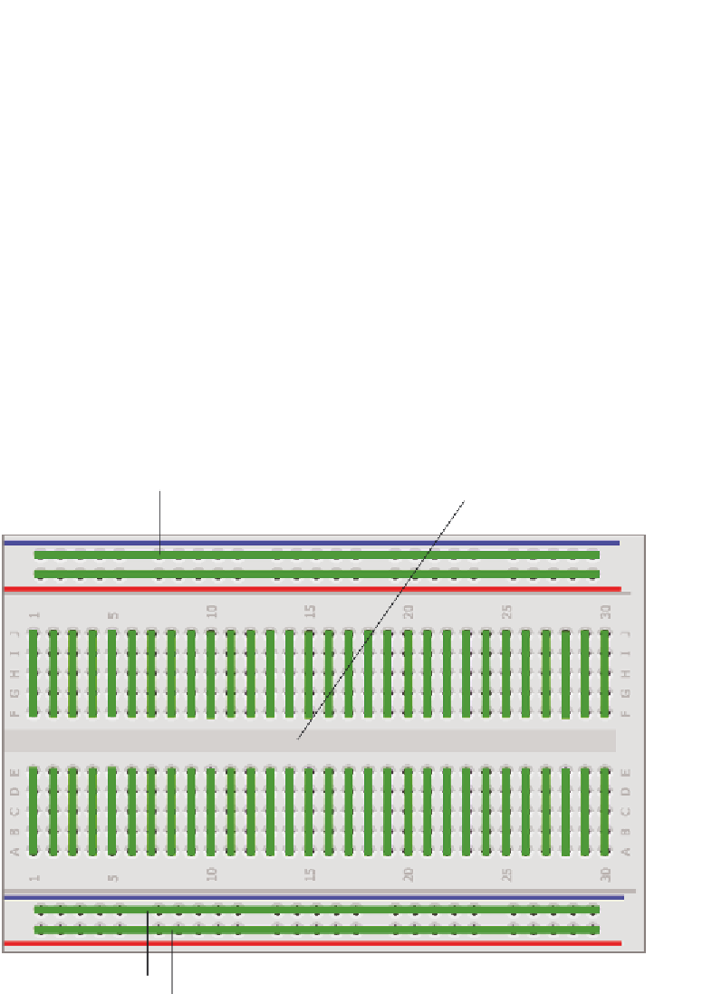
It is important to understand how breadboards work so that you can use them
effectively for the projects in this topic. A
breadboard
is a simple prototyping
tool that easily allows you to wire up simple circuits without having to solder
together parts to a custom printed circuit board. First, consider the blue and
red lines that run the length of the board. The pins adjacent to these color-
coded lines are designed to be used as power and ground buses. All the red
pins are electrically connected, and are generally used for providing power. In
the case of most Arduinos and the projects in this topic, this will generally be
at 5V. All the blue pins are electrically connected and are used for the ground
bus. All the vertically aligned pins are also connected in rows, with a division
in the middle to make it easy to mount integrated circuits on the breadboard.
Figure 2-1 highlights how the pins are electrically connected, with all the thick
lines representing connected holes.
Ground bus
Power bus
Prototyping area
Ground bus
Power bus
Figure 2-1:
Breadboard electrical connections
Search WWH ::

Custom Search