Hardware Reference
In-Depth Information
The rest of the pins are all general-purpose I/O. Each is mapped to a unique
pin number in the Arduino software so that you don't have to worry about the
port letter and number.
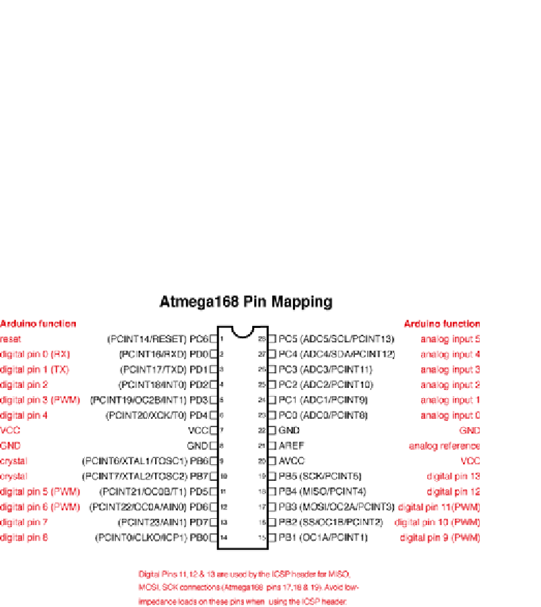
The labels in parentheses represent alternative functions for each pin. For
example, pins PD0 and PD1 are also the Universal Synchronous/Asynchronous
Receiver/Transmitter (USART) Receive (RX) and Transmit (TX) pins, respec-
tively. Pins PB6 and PB7 are the crystal connection pins (XTAL). In the case of
the Arduino Uno, an external 16 MHz ceramic resonator is connected to these
pins, so you cannot use these for general-purpose I/O. If you have trouble
deciphering the pin labels, you can usually learn more about what they mean
by searching the rest of the datasheet for those terms. The Arduino website
has a diagram illustrating how the ATMega pins are connected to numbered
pins on the Arduino board. You can find it at
http://arduino.cc/en/Hacking/
PinMapping168
, and it is shown in Figure A-4.
Figure A-4:
Arduino ATMega Pin Mapping
UnderstandingtheArduinoSchematic
Perhaps one of the best ways to learn about electrical design is to analyze the
schematics of existing products, such as the Arduino. Figure A-4 shows the
schematic for the Arduino Uno.
Search WWH ::

Custom Search