Hardware Reference
In-Depth Information
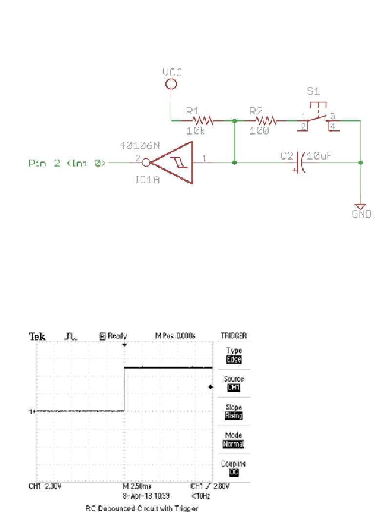
The output from your debounce circuit will go through one of these inverting
Schmitt triggers before finally being fed into the Arduino. The resulting circuit
diagram looks Figure 12-6.
Figure 12-6:
Final step for creating a debounce circuit: adding an inverting Schmitt trigger
Because this is an inverting trigger, the signal will also be flipped. So, when
the button is held down, the final signal will be a logical high, and vice versa.
So, in the next step, when you write the code, you want to look for a rising edge
to detect when the button is first pressed. The final output signal looks like a
nice, clean, bounce-free signal (see Figure 12-7).
Figure 12-7:
Final output of debounce circuit
Search WWH ::

Custom Search