Hardware Reference
In-Depth Information
It doesn't matter what kind of Arduino you use in your system, but it is
important to note that serial communication on boards like the Leonardo works
differently than on the Uno. The Leonardo and Micro have a single MCU to
control serial communication and program execution, whereas the Uno and
Mega have separate processors. To demonstrate these differences, I chose to use
a Leonardo for the transmitter. The circuit for either type of board is the same;
software differences are addressed next.
Because the transmitter will presumably not be near a computer, choose one
of the power options from earlier in the chapter that doesn't require power over
USB from a computer. In the video demo, I used a 9V battery connected to the
barrel jack connector. If you want this to be a bit more permanent, you might
want to power the circuit using a DC wall adapter.
TIP
Ifyouareinterestedinmakingsomethingabitmorepolished,youcouldbuya
large,wiredpushbuttonandwireitthroughthewalltotheArduinoontheotherside.
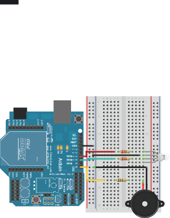
ReceiverHardware
Next, build the component that will notify you when the transmitter's button
is pressed. This will be your receiver. The hardware for this circuit consists of
an Arduino with an XBee shield and radio, an RGB LED, resistors, and a small
Piezo speaker. Follow the wiring diagram in Figure 11-21. Note that only the
red and green LEDs are used in the sketch, so adding a resistor for the blue LED
resistor is not necessary. You could also install a potentiometer in-line with the
speaker to make the volume adjustable.
Figure 11-21:
Wireless doorbell receiver

Search WWH ::

Custom Search