Hardware Reference
In-Depth Information
SettingUptheHardware
The hardware setup for this project is a conglomeration of previous projects. If
you want the fan to have some oomph, you can drive it with a transistor and
an external voltage supply (like the DC motor from Chapter 4, “DC Motors,
Transistors, and Servos”). A low-power DC fan hooked directly to a 5V I/O pin
will suffice to show that it spins when it should. It will be accelerating slowly
enough that you don't need to worry too much about inductive spikes. If you
actually want it to make a breeze, use the same schematic that you used for
driving a DC motor in Chapter 4 (see Figure 4-1).
To wire the project, leave the LCD and trim potentiometer in the same loca-
tion they were in for the previous example.
The two buttons have one side connected to power; the other side is connected
to ground through 10kΩ pull-down resistors and to the Arduino.
The speaker is connected to an I/O pin through a 150Ω resistor and to ground.
The frequency of the sound will be set in the program.
You hook up the I
2
C temperature sensor exactly as you did in Chapter 8.
Placing it in front of the LCD's contrast potentiometer allows you to conserve
some breadboard space and to fit everything onto the same half-size bread-
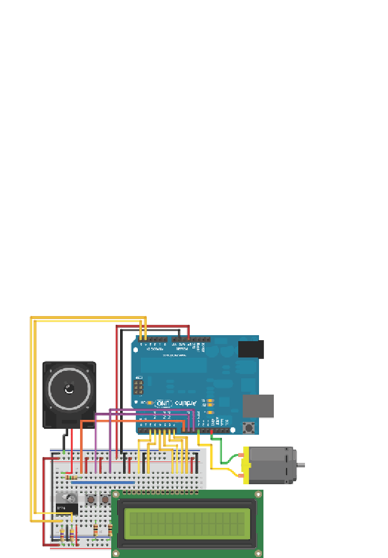
board that you've been using so far. The diagram in Figure 10-3 shows the
complete wiring setup with everything you need to create this project. The
symbol for the TC74 temperature sensor has been made partially transparent
so that you can see the potentiometer behind it.
Figure 10-3:
LCD thermostat system
Search WWH ::

Custom Search