Hardware Reference
In-Depth Information
the next 2 bits are the first 2 data bits, which should always be 0 because the
potentiometer can only be as high as 128.
This is all the information you need to wire the DigiPot correctly and to
send SPI commands to it from your Arduino. Now, you wire it up to control
the brightness of some LEDs.
SettingUptheHardware
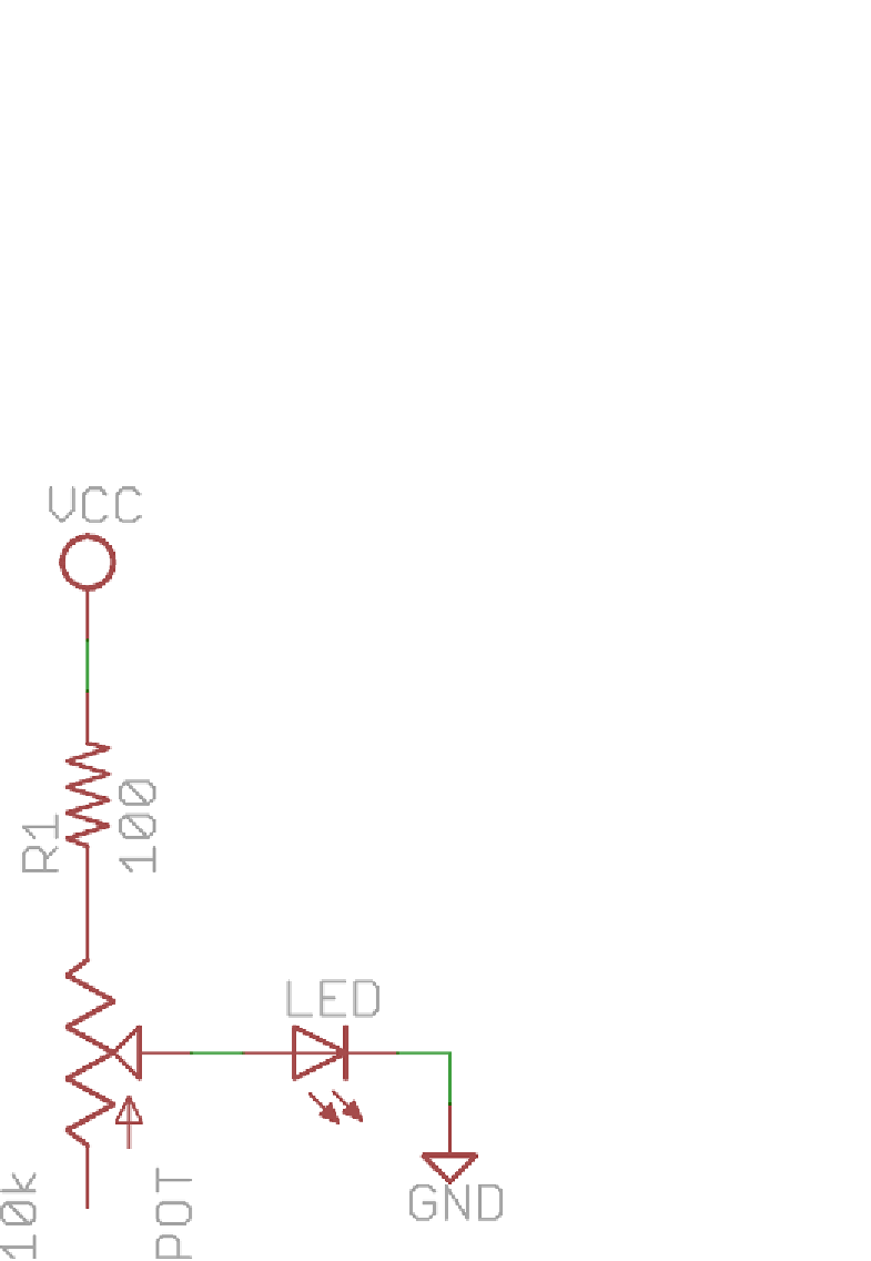
To fully flesh out your knowledge of SPI communication, you'll use two MCP44231
DigiPot ICs, for a total of four controllable potentiometer channels. Each one
is used to control the brightness of two LEDs by varying the series resistance
in-line with the LED. When used in this fashion, you need to use only two
terminals of each potentiometer. One end of each potentiometer connects to
the 5V rail (through a resistor), and the wiper pin connects to the anode of the
LED. Consider the schematic Figure 9-5, which shows this connection scheme.
Figure 9-5:
Potentiometer LED setup
Search WWH ::

Custom Search