Hardware Reference
In-Depth Information
Table 9-1:
SPI Communication Modes
SPI MODE
CLOCk POLARITY
CLOCk PHASE
Mode 0
Low at Idle
Data Capture on Clock Rising Edge
Mode 1
Low at Idle
Data Capture on Clock Falling Edge
Mode 2
High at Idle
Data Capture on Clock Falling Edge
Mode 3
High at Idle
Data Capture on Clock Rising Edge
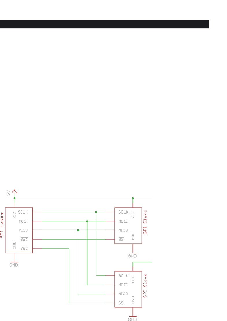
SPIHardwareandCommunicationDesign
The SPI system setup is relatively simple. Three pins are used for communicat-
ing between a master and all slave devices:
■
Shared/Serial Clock (SCLK)
■
Master Out Slave In (MOSI)
■
Master In Slave Out (MISO)
Each slave device also requires an additional slave select (SS) pin. Hence, the
total number of I/O pins required on the master device will always be 3 +
n
,
where
n
is the number of slave devices. Figure 9-1 shows an example SPI system
with two slave devices.
Figure 9-1:
SPI reference hardware configuration


Search WWH ::

Custom Search