Hardware Reference
In-Depth Information
ConvertingBetweenBinaryandDecimalFormats
In Listing 7-1, the LED state information was written as a binary string of digits.
This string helps you visualize which LEDs will be turned on and off. However,
you can also write the pattern as a decimal value by converting between base2
(binary) and base10 (decimal) systems. Each bit in a binary number (starting
from the rightmost, or least significant, bit) represents an increasing power of 2.
Converting binary representations to decimal representations is very straight-
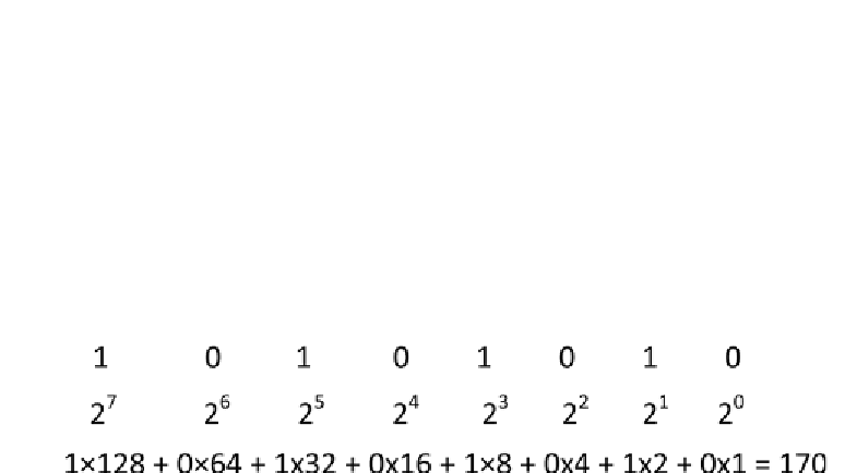
forward. Consider the binary number from earlier displayed in Figure 7-5 with
the appropriate decimal conversion steps.
Figure 7-5:
Binary to decimal conversion
The binary value of each bit represents an incrementing power of 2. In the
case of this number, bits 7, 5, 3, and 1 are high. So, to find the decimal equiva-
lent, you add 2
7
, 2
5
, 2
3
, and 2
1
. The resulting decimal value is 170. You can prove
to yourself that this value is equivalent by substituting it into the code listed
earlier. Replace the
shiftOut()
line with this version:
shiftOut(SER, CLK, MSBFIRST, 170);
You should see the same result as when you used the binary notation.
ControllingLightAnimationswithaShiftRegister
In the previous example, you built a static display with a shift register. However,
you'll probably want to display more dynamic information on your LEDs. In
the next two examples, you use a shift register to control a lighting effect and
a physical bar graph.
Buildinga“LightRider”
The light rider is a neat effect that makes it looks like the LEDs are chasing each
other back and forth. Continue to use the same circuit that you used previously.
The
shiftOut()
function is very fast, and you can use it to update the shift

Search WWH ::

Custom Search