Hardware Reference
In-Depth Information
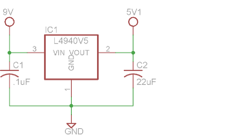
Figure 4-11:
5V Linear regulator schematic
Note the capacitors on each side of the regulator. These are called
decoupling
capacitors
; they are used to smooth out the voltage signal from each supply volt-
age by charging and discharging to oppose ripples in the voltage. Most linear
regulator datasheets include a suggested circuit that includes ideal values and
types for these capacitors based on your use case scenario. Also keep in mind
that the 5V rail created by this regulator should be kept separate from the 5V
power rail of the Arduino. Their grounds, however, should be tied together.
Using all this information, it's time to wire up a servo. Referencing Figure 4-12,
wire the servo, the 5V regulator, and the potentiometer. Leave the potentiometer
connected to analog pin 0, connect the servo control pin to pin 9, and ensure
that the 5V regulator supplies the servo's power.
While wiring, keep in mind a few important things. First, ensure that you
have the orientation of the regulator correct. With the metal tab on the side
farthest from you, connect the battery to the leftmost pin, the ground to the
center pin, and the servo's power line to the right pin. Second, if using polarized
electrolytic capacitors (as in Figure 4-12), make sure to put them in the correct
direction. The stripe indicates the negative terminal and should be connected
to the common ground. Make sure that the pins don't touch; otherwise, it could
cause a short. After you're all wired up, move on to the next section to learn
how to program the servo controller.
Search WWH ::

Custom Search