Hardware Reference
In-Depth Information
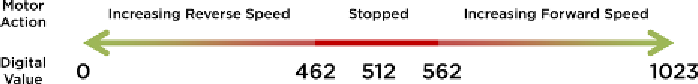
are converted to digital values between 0 and 1023. Refer to Figure 4-8 to better
understand the control scheme and compare that with the preceding loop code.
Figure 4-8:
Motor control plan.
When the potentiometer is within the 100 units surrounding the midpoint,
the
brake
function is called. As the potentiometer value increases from
562
to
1023
, the speed forward increases. Similarly, the speed increases in the reverse
direction between potentiometer values of
462
and
0
. The
map
function should
look familiar to you from the previous chapter. Here, when determining the
reverse speed, note the order of the variables:
461
is mapped to
0
, and
0
is
mapped to
255
; the
map
function can invert the mapping when the variables
are passed in descending order. Putting the loop together with the functions,
and the
setup
, you get a completed program that looks like the one shown in
Listing 4-3. Ensure that your program matches the one here and load it onto
your Arduino.
Listing 4-3:
H-Bridge Potentiometer Motor Control—hbridge.ino
//Hbridge Motor Control
const int EN=9; //Half Bridge 1 Enable
const int MC1=3; //Motor Control 1
const int MC2=2; //Motor Control 2
const int POT=0; //POT on Analog Pin 0
int val = 0; //for storing the reading from the POT
int velocity = 0; //For storing the desired velocity (from 0-255)
void setup()
{
pinMode(EN, OUTPUT);
pinMode(MC1, OUTPUT);
pinMode(MC2, OUTPUT);
brake(); //Initialize with motor stopped
}
void loop()
{
val = analogRead(POT);
//go forward
if (val > 562)
{

Search WWH ::

Custom Search