Geology Reference
In-Depth Information
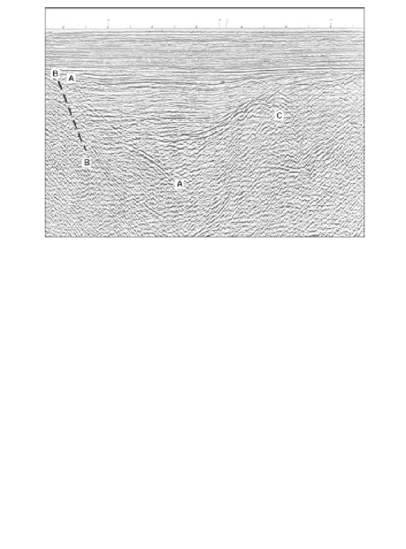
Figure 12.8
Geometric distortion on seismic sections. The image is of a
small graben structure beneath an unconformity. The position of the true
fault plane BB (indicated by the dashed line) can be estimated from the
positions of the terminations of the sub-horizontal reflectors representing
the sediment fill within the graben. The event AA is the seismic image of
BB, but is displaced because the techniques used to display the data assume
that reflections are generated from points vertically beneath the surface
points, whereas they are actually generated by normal-incidence rays that
are inclined to the vertical if reflected from dipping interfaces. The reflections
from the fault and the opposite side of the graben cross over near the lower
symbol 'A', forming a 'bow-tie'. Convex-upward reflections near point 'C'
are diffraction patterns generated by the edges of fault blocks. See discussion
in Section 10.3.2.
and field crews should always be on the lookout for opportunities to measure
vertical velocities directly.
12.2.6 Geometric distortion
Seismic reflection data are normally presented as sections prepared by play-
ing out, next to each other and vertically down the sheet of paper, the traces
from adjacent CMP gathers. Such sections are subject to geometric distor-
tion. Artefacts such as displaced reflectors, diffraction patterns and 'bow-
ties', described in Section 10.3.2 as affecting radar sections, also appear on
seismic imagery, as shown in Figure 12.8.