Geology Reference
In-Depth Information
Shot D
Shot C
Shot B
Shot A
d
Depth points, Shot A
Depth points, Shot B
Depth points, Shot C
Depth points, Shot D
∆
∆
∆
∆
∆
∆
∆
∆
∆
∆
∆
∆
∆
∆
∆
∆
∆
∆
∆
∆
∆
∆
∆
∆
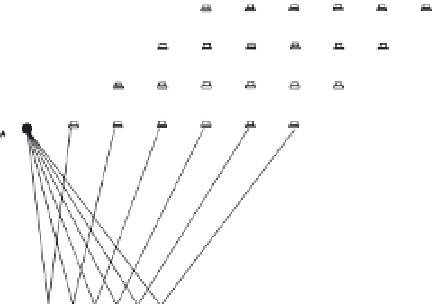
Figure 12.6
Common mid-point (CMP) schematic, for three-fold cover with
a six-channel system. Shot-points A, B, C and D are progressively one
geophone group interval further to the right. Note that the distance between
reflection points (depth points) on the interface is only half that between
the geophone groups on the surface. Shots A and D have no depth points in
common.
The geometry of a CMP gather (Figure 12.7) differs from that for single-
fold coverage since the shot-point positions as well as the geophone positions
change, and the effect of dip is therefore different. The aim of stacking is
to produce a noise-reduced seismic trace that approximates to the normal
incidence trace, i.e. to the trace that would have been produced had the source
and detector been coincident at the mid-point, and the 'depth' associated
with this trace is, again, the slant distance
d.
However, in contrast to the
situation shown in Figure 12.3, the minimum time is associated with the
normal incidence ray, which travels the distance 2
d
. The equations shown in
Figure 12.7 replace the offset '
x
' of the NMO equation with
x
.cos(
α
), where
the interface dips at an angle
, and the velocity deduced from a CMP stack
is therefore equal to
V
/
cos(
α
). This is always greater than
V
, but by how
much is generally not known, at least in the early stages of work in an area,
because
α
is generally not known.
The initials CMP replaced an earlier acronym, CDP (
common depth
point
), used for the same method. The newer term is preferable, because
labelling the depth points (reflection points) as 'common' implies that all
the reflections in a gather have come from the same point on the subsurface
interface, which is true only for horizontal interfaces.
α