Geology Reference
In-Depth Information
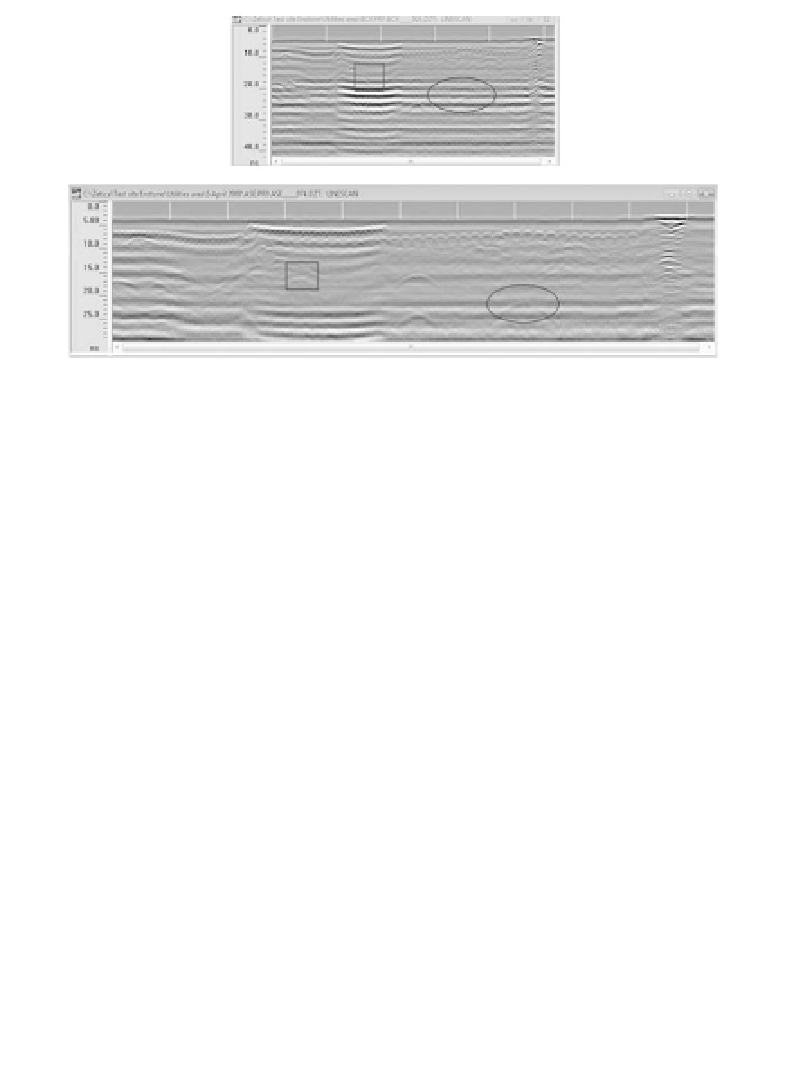
Figure 10.16
Radargrams from incorrectly and correctly set-up ground
penetrating radar (GPR) systems. In the upper example the targeted features
(outlined) are all but invisible. The improved set-up below, with 2.5 times the
scans per metre and a 30% reduced range, reveals the subtle, but important,
features sought.
The high repetition rates possible with radar systems allow large numbers
of signals to be recorded at each transmitter/receiver set-up and to be stacked
to reduce the effects of random noise. The decision as to how many repe-
titions should be used is one that, inevitably, must be made in the field. At
the very least, the number of repetitions used should be the maximum that
is possible before reading time begins significantly to affect productivity.
Dipolar transmitter and receiver antennas are most commonly set out side
by side, but end-on and even broadside (orthogonal) configurations are also
used. Antennas should be orientated parallel to the target strike-direction,
if this is known (see Section 10.1.8). Freely available, one-dimensional
(horizontally layered Earth) modelling software provides a useful way of
testing assumptions, identifying multiple paths, reverberations and polar-
ity changes, and confirming the ranges and optimum central frequencies
required to resolve the expected targets (Figure 10.17).
10.2.4 Interference in GPR surveys
Even when depth penetration, reflectivity and resolution seem satisfactory,
environmental problems can prevent success in a GPR survey. Radio trans-
mitters are potential sources of interference, and powerful radio signals can
overwhelm (
saturate
) receiver electronics. The presence of metal objects
in the subsurface can also be disastrous if these are not the survey targets.
Reflections can come from objects away to the side (
sideswipe
), and may be