Geology Reference
In-Depth Information
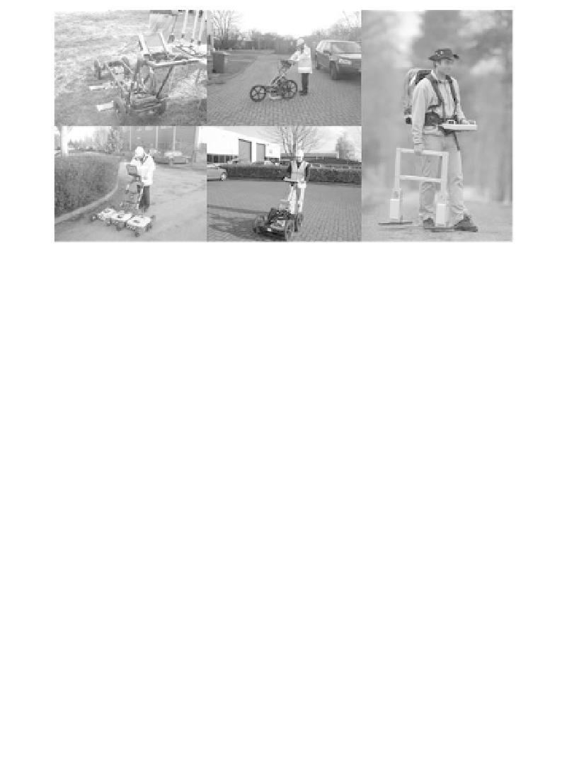
Figure 10.13
Examples of commonly available radar systems utilising
ground-coupled dipole or bow-tie antennas.
of target investigation depths. Relatively low permittivity materials are as-
sumed for this table. For high permittivity and/or conductive materials, or
materials containing a high number of scatterers (clutter), penetration will
be significantly reduced.
10.2.1 Instrumentation
Ground penetrating radar systems (Figures 10.13 and 10.14) consist of con-
trol and recorder units (CRUs) linked to receiver and transmitter units, each
of which is in turn linked to one or more antennas. Metal wires are less effi-
cient conductors of alternating current at radar frequencies, and signals are
usually transmitted to and from the CRUs via optical fibres. These have the
advantage of immunity from electrical interference, but are more delicate
than wires and less easily repaired when damaged. Some commercially avail-
able fibre cables are protected by black sleeving that makes them almost in-
visible when laid out on the ground, so plenty of spares must be taken into the
field to replace breakages.
The settings on the CRU determine the radar frequency, the time pe-
riod (
window
) during which data are to be recorded and the number of
individual traces to be stacked. Central frequencies of 25, 50, 100 and
200 MHz would be typical for geological applications, with recordings
made over time windows of between 32 and 2048 ns. The frequencies used
for scanning engineering structures are usually in the range from 400 to
4000 MHz, over time periods of between 10 and 70 ns. Modern CRUs are
equivalent to powerful personal computers, and much signal processing can