Geology Reference
In-Depth Information
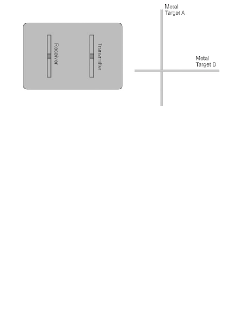
Figure 10.12
Schematic showing the layout of parallel transmitter and
receiver dipole antennas in a single housing in relation to metal targets
A and B.
(and productivity) in cases where the target orientation is unknown. How-
ever, if the object of the exercise is to image features below a metal pipeline
or a concrete slab with reinforcement bars (
rebars
), then the antennas are
best orientated perpendicular to the pipe or bar direction, to minimise their
influence on the signal from the target.
As in Figure 10.12, most GPR systems utilise separate receiver and trans-
mitter antennas, which may be mounted separately or integrated into a single
module. Separability is desirable even if the spacing is to be kept constant
in a given survey, because its optimum value depends on environment and
target depth as well as on frequency and transmitter size. A single housing
is, however, almost essential for continuous profiling, but it is then necessary
to protect the receiver antenna from the high level of the transmitted signal.
Reducing cross-coupling between transmitter and receiver antennas is an
important aim of GPR system design.
Much effort is now going into designing antennas that are shielded to
maximise the downward-looking signal and reduce the spurious responses
from above-ground targets. No shielding is ever perfect and signal leakage
can and will occur, despite claims to the contrary. These new antennas are
mainly variants of resistively loaded dipoles and spiral and TEM horns.
10.1.9 Pulse stacking
An ideal GPR impulse system would transmit a pulse into the ground and
display the convolved ground and receiver antenna response as a single